Foxcom (digital) summary, Mounting to the actuator (valve), Connection and startup – Badger Meter SRD/SRI Valve Positioners User Manual
Page 11: System configuration, Foxcom (digital) summary 11
FOXCOM (DIGITAL) SUMMARY
Mounting to the Actuator (Valve)
The SRD960 can be mounted to stroke or rotary actuators
Connection and Startup
Connect the pneumatic tubing Upon connection of supply air and a voltage source of, for example, 24V DC to the input
terminals (pay attention to polarity), an initial startup can be carried out without any further equipment
Use the local push-buttons to change basic parameters such as type of actuator, side of installation, valve opens/closes with
increasing setpoint value, and characteristics curve of the valve (values set ex-factory: stroke actuator, mounting side: left,
valve opens with increasing setpoint value, linear characteristics curve)
Thereafter, an AUTOSTART can be performed during which the SRD960 determines independently the geometric data of the
actuator as well as control parameter, to ensure an optimized operation with the attached valve
FoxCom Version
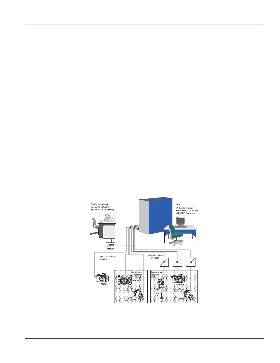
The positioner can be operated either locally via PC or via I/A Series System (FoxCom)
System Configuration
When using Communication (a digital signal with constant amplitude), make sure that the connected outputs, buffer
amplifier and barriers are compatible with the frequency ranges used In addition to the load, the AC impedances
requirements must be met Therefore, it is recommended that only the specified amplifier, barrier and configuration device
is used
To prevent crosstalk between lines and reduce disturbances through electromagnetic influences, it is recommended that
twisted-pair shielded lines be used, with a diameter of AWG 22…14 (0 3…2 5 mm
2
) and a maximum capacity of 100 pF/m
The line capacities and connected devices may not exceed the maximum values listed for a particular FoxCom protocol
All components connected to the SRD in an explosion-hazard area require an Ex-Approval The applicable limit values must
not be exceeded These limit values also have to be adhered to when connecting additional capacitances, inductances,
voltages and currents
Figure 5: FOXCOM
Page 11
FoxCom (Digital) Summary
August 2014
POS-UM-00009-EN-02