Badger Meter SRD/SRI Valve Positioners User Manual
Page 26
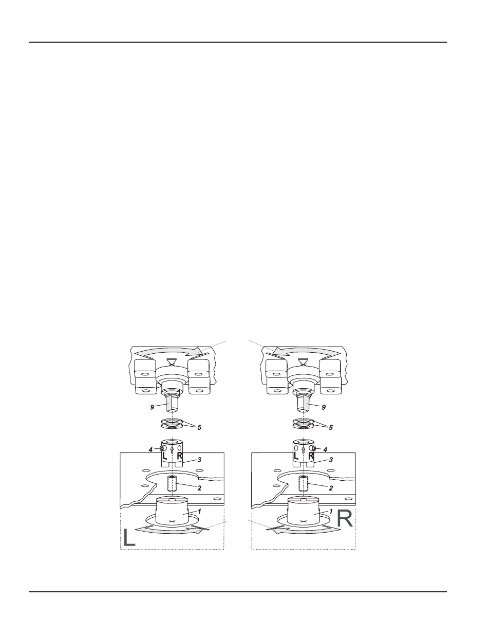
Preparation of the Actuator
First, prepare the rotary adaptor:
• For attachment to a counter-clockwise or left-turning
actuator, secure the stud screw 4 in the threaded hole L
of the rotary adaptor; hole R remains open See the left
graphic in
• For attachment to a clockwise or right-turning actuator,
secure the stud screw 4 in the threaded hole R of the
rotary adaptor; hole L remains open See the right graphic
Place the rotary adaptor 3 with two washers 5 on the
feedback shaft 9 of the positioner against the stop
NOTE:
N
When the product temperature rises, the drive shaft
1 becomes longer Therefore, the rotary adaptor
3 must be mounted so that approximately 1 mm
(0 04 in ) of clearance results between the drive
shaft 1 and the rotary adaptor 3 This is achieved by
placing an appropriate number of washers 5 on the
feedback shaft stub 9 before attaching the rotary
adaptor Two washers should result in a clearance of
1 mm
Screw and tighten the bolt in the coupling against the flat
part of the feedback shaft (do not screw against thread!)
Finally, turn the feedback shaft in such a way that the arrow
of the coupling points to the arrow of the SRD housing
Beginning and end positions of the actuator drive shaft 1 and
feedback shaft 9 are marked in the left graphic in
(counter-clockwise rotating actuator) and in the right graphic
in
(clockwise rotating actuator) by arrows for the
respective direction of rotation
The feedback shaft is now in the normal position
corresponding to the failsafe position of the actuator
Mounting of Positioner
SRD and actuator are in FAILSAFE position
Turn set screw 2 into shaft 1
Attach the SRD on the console in such a way that the catch of
coupling 3 is guided into the groove of shaft 1 Be careful not
to shift shafts 1 and 9 and that both shafts are exactly flush
The set screw 2 can assist in alignment
Fasten the positioner to the bracket by means of 4 lock
washers and 4 screws M6 x 12
SRD
Rotary actuator
Figure 27: Mounting if actuator is left-rotating
SRD
Rotary actuator
Figure 28: Mounting if actuator is right-rotating
Direction
of rotation
0 --> 100 %
of actuator
shaft
1
Direction
of rotation
0 --> 100 %
of feedback
shaft
9
Figure 30: Positioner mounting
Page 26
Mounting to Linear Actuators
August 2014
POS-UM-00009-EN-02