Troubleshooting guide, Errors detected during initialization, Errors detected during self-test – Badger Meter SRD/SRI Valve Positioners User Manual
Page 60: Troubleshooting guide 60
TROUBLESHOOTING GUIDE
The components of the positioner are under constant
surveillance by the installed micro controller Errors detected
are displayed in LCD or indicated by the LEDs
Certain conditions (such as “Stroke limitation active”) are
displayed in LCD or indicated by the LEDs as message
Errors Detected During Initialization
After startup or reset, several initialization phases are passed
through which are shown in LCD or in the green LEDs If this
phase stops an error was detected
If after renewed reset
1)
the indicator stops at error code,
the device is probably defective and should be sent to the
manufacturer for repair Stating the error code will help the
Repair and Service Dept
1) Execute reset by simultaneous pressing () (–) (+) keys, or by turn-off and restart of
input signal
LED Error Codes (with LCD in true text)
LEDs
Description
red
green
M
1
2
3
4
-
1
1
1
1 Micro controller functional test
-
1
1
1
- Micro controller RAM test
-
1
1
-
1 Micro controller ROM test
-
1
1
-
- initialize operating system
-
1
-
1
1 initialize monitor
-
1
-
1
- initialize interfaces
-
1
-
-
1 initialize timer
-
1
-
-
- initialize EEPROM
-
-
1
1
1 initialize data
-
-
1
1
- initialize ADC
-
-
1
-
1 initialize communication
-
-
1
-
- initialize local operation
-
-
-
1
1 start background process
-
-
-
1
- check options and start
-
-
-
-
1 start operating system
1 = LED constant light
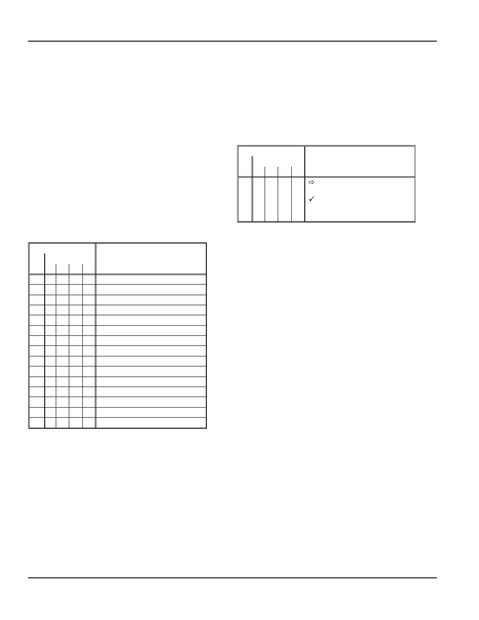
LED indication for diagnosis, errors:
The following combinations are possible:
After start / reset: (X X X X = error code)
M 1 2 3 4
- X X X X Error detected during Init
s. 11.1
Device in normal operation:
M 1 2 3 4
1 -
-
-
-
Cyclical self-test detects errors
s. 11.2
-
-
-
-
-
diagnosis without LED inform
s. 11.3
¾ x x x x flashing: message
s. 11.4
Errors Detected During Self-Test
During cyclical self-test, certain components of the SRD are
under constant surveillance If necessary, trouble detection
is initiated in the electronics LCD or the red LED; output y1
becomes pressureless (‘fail safe position’)
If after reset
1)
the display shows the error again the device
is probably defective and should be sent to manufacturer
for repair
LEDs
Description
red
green
M
1
2
3
4
1
-
-
-
-
Red LED lights up const.
RAM / EPROM fault
Actuate “Reset”; send device-
to manufacturer if error re-
appears
1 = LED constant light
1) Execute reset by simultaneous pressing () (–) (+) keys, or by turn-off and restart of
input signal
Page 60
Troubleshooting Guide
August 2014
POS-UM-00009-EN-02