Namur mounting, right hand, Namur mounting, right hand 21 – Badger Meter SRD/SRI Valve Positioners User Manual
Page 21
NAMUR Mounting, Right Hand
Right-hand mounting is done if, for instance, left-hand
mounting is not possible for structural reasons
Applicable to actuators with cast yoke or pillar yoke
according to NAMUR (DIN IEC 534-6)
Mounting the positioner with pneumatic connections on the
right side and electrical connections on the lower left side
Figure 18: NAMUR mounting, right hand
Attachment of the positioner to the actuator is made to the
right using the mounting bracket and feedback lever for a
NAMUR mount Use:
• Attachment kit EBZG -H for a cast yoke, or
• Attachment kit EBZG -K for a pillar yoke
The side outputs I (or I and II) are used The rear output I is
closed by means of a lock screw 522 588 013
Pneumatic connections: Do not use Teflon tape for sealant
The fine fibers could disturb the function of the SRD Use only
Loctite® #243 for sealant and apply it only to the male thread
Screw-type glands for electrical connections are positioned
on the lower side Any unused threaded holes are plugged
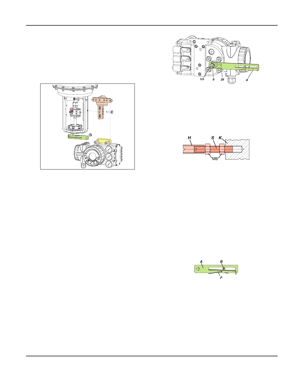
Preparation of the Positioner
Rotate the shaft stub of shaft 9 so that the flat on the shaft
stub is perpendicular to the arrow 26 on the housing (detail,
“NAMUR Mounting Dimensions, Right Hand” on page 22
Fasten the feedback lever A to the shaft by means of spring
washer and nut M8
Figure 19: Positioner preparation
Preparation of the Actuator
Screw the carrier bolt to the stem connector and lock it by
means of a counter nut
A carrier bolt with an adjustable length is used to be able to
screw on various coupling pieces
Figure 20: Actuator preparation
It consists of a stud S, which is screwed into the coupling
piece K (with 3 mm Allen key) and locked with a lock nut
M6 The threaded sleeve H is screwed onto it and locked
with a lock nut M6 Make sure that the bolt is adjusted to the
right length!
Fasten the mounting bracket to the right side of the yoke
For a cast yoke, use a screw M8 x 30; for a pillar yoke, use two
U-bolts and two nuts
Mounting of the Positioner
Fasten the positioner to the mounting bracket using two
spring washers and two screws M8 x 80
The carrier bolt B is in the slot of the feedback lever A and the
compensating spring F touches the carrier bolt
Figure 21: Positioner mounting
For optimum use of the positioner operating range, adjust
the arrangement according to the following procedure
before fixing At an actuator position in the middle of travel
range, the feedback lever position should be perpendicular
to the actuator stem and the angle range should be between
−10…10° and −45…45°
Fasten the positioner to the mounting bracket so that a
suitable angle range is selected Make the pneumatic and
electrical connections after adjusting the position
Page 21
Mounting to Linear Actuators
August 2014
POS-UM-00009-EN-02