Input, Power supply, Blueport® front interface – West Control Solutions KS 45 User Manual
Page 72: Bus interface (optional), System interface, Environmental conditions, Version 1 version 2 power relay 1
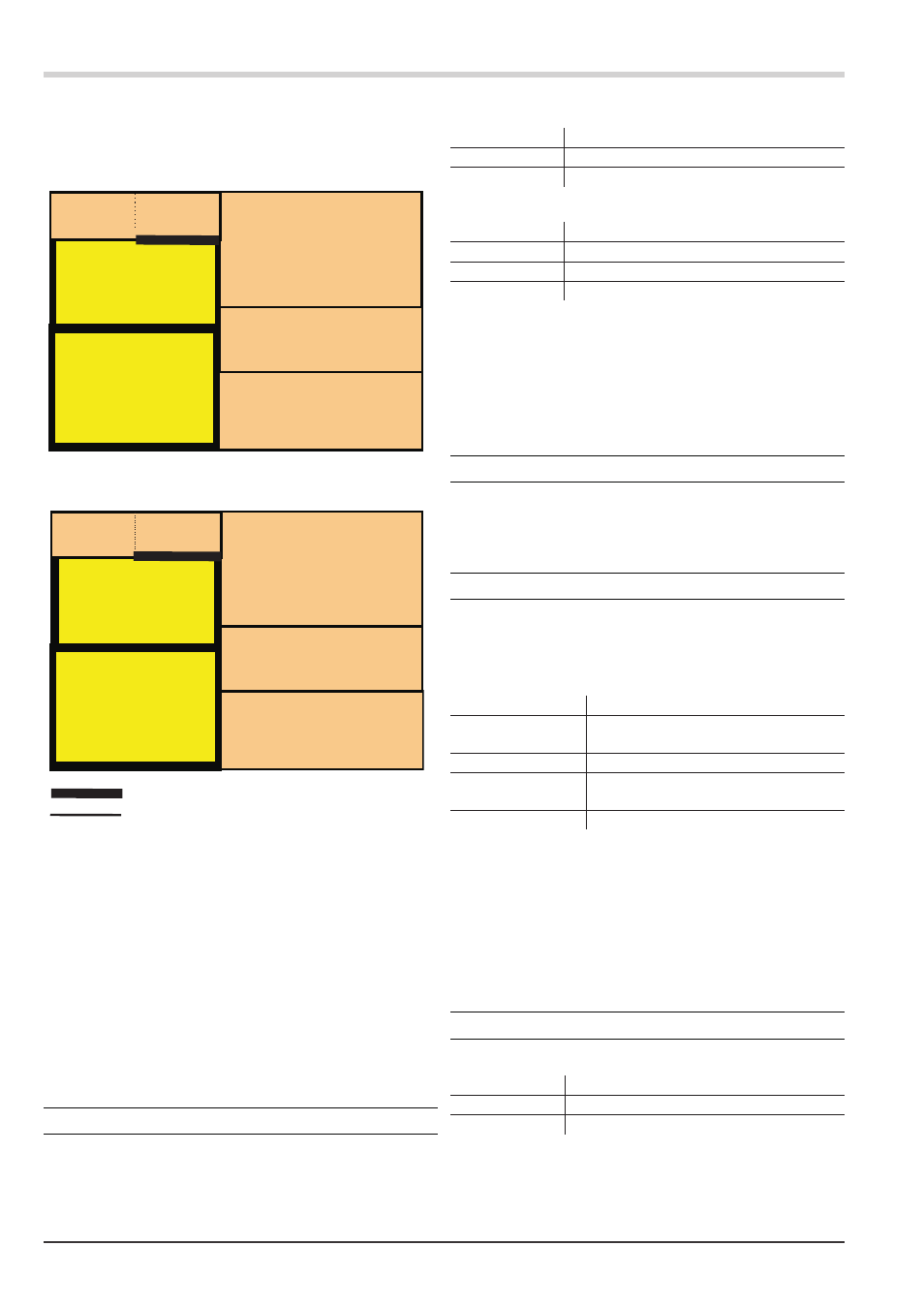
Galvanic isolation
Galvanic isolation between inputs and outputs as well as from
the supply voltage is provided.
Test voltages:
Between power supply and inputs/outputs:
2,3 kV AC, 1 min
Between inputs and outputs:
500 V AC; 1min
Max. permissible voltages:
Between inputs/outputs
against earth:
ß 33 V AC
POWER SUPPLY
Depending on ordered version:
AC supply
Voltage:
90...260 V AC
Frequency:
48...62 Hz
Consumption:
approx. 7 VA max.
Universal supply 24 V UC
AC supply:
18...30 V AC
Frequency:
48...62 Hz
DC supply:
18...31 V DC
Consumption:
approx. 4 VA / 3W max.
* Instruments with optional system interface:
energization is via the bus connector from field bus coupler or
power supply module
Behaviour with power failure
Configuration and parameter settings:Permanent storage in EEPROM
BLUEPORT® FRONT INTERFACE
Connection to the controller front via a PC adapter (see ‘Additional
Accessories’). The BlueControl
®
software enables the KS 45 to be
configured, parameters set, and operated.
BUS INTERFACE (OPTIONAL)
RS 485
Connection via bus connector fitted in the top-hat rail. Screened
cables should be used.
Galvanically isolated
Type:
RS 485
Transmission speed: 2,400, 4,800, 9,600, 19,200, 38,400
bits/sec
Parity:
even, odd, none
Number of controllers
per segment:
32
Address range:
1...247
Number of controllers per bus segment: 32
Protocol
MODBUS RTU
SYSTEM INTERFACE
For connection to field bus couplers (see system components)
Connection via bus connector fitted in the top-hat rail.
ENVIRONMENTAL CONDITIONS
Protection mode
Front panel:
IP 20
Housing:
IP 20
Terminals:
IP 20
Technical data
72
KS 45
safety isolation
functional isolation
Version 1
Version 2
power
relay 1
input
1
input 2
di 1 (contact)
di 1 (option
optocoupler
output 3
RS 485
system
relay 2
front interface
power
relay 3
input 1
input 2 (HC)
di 1 (contact)
di 1 (option
optocoupler
optocoupler 1
RS 485
system
optocoupler 2
front interface