5 continuous controller (inverse) 41, Continuous controller 41, Inh.1 inl.1 sp.lo sp sp.hi out.3â inp.1ê – West Control Solutions KS 45 User Manual
Page 41
7.2.5
Continuous controller (inverse)
ConF / Cntr: SP.Fn
=
0
setpoint controller
C.Fnc
=
1
continuous controller (PID)
C.Act
=
0
inverse action (e.g. heating applications)
ConF / Out.3: O.tYP
=
1 / 2
Out.3 type ( 0/4 … 20mA )
Out.0
=
-1999...9999
scaling analog output 0/4mA
Out.1
=
-1999...9999
scaling analog output 20mA
PArA / Cntr: Pb1
=
0,1...9999
proportional band 1 (heating)
in units of phys. quantity (e.g. °C)
ti1
=
1...9999
integral time 1 (heating) in sec.
td1
=
1...9999
derivative time 1 (heating) in sec.
t1
=
0,4...9999
min. cycle time 1 (heating)
PArA / SEtP: SP.LO
=
-1999...9999
setpoint limit low for SPeff
SP.Hi
=
-1999...9999
setpoint limit high for SPeff
g
For direct action of the continuous controller, the controller action must be changed
(
ConF / Cntr / C.Act = 1 ).
g
To prevent control outputs
Out.1 and Out.2 of the continuous controller from switching simultaneously,
the control function of outputs
Out.1 and Out.2 must be switched off ( ConF / Out.1 and Out.2 / Y.1
and
Y.2 = 0 ).
Controlling
KS 45
41
Configuration examples
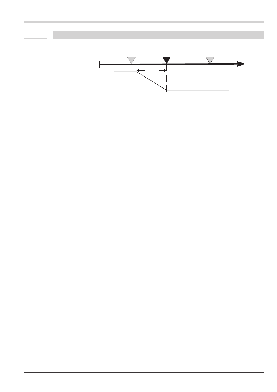
InH.1
InL.1
SP.LO
SP
SP.Hi
Out.3Â
InP.1Ê
20 mA
0/4 mA
PB1