4 manual tuning 46, Manual tuning 46, Parameter adjustment effects – West Control Solutions KS 45 User Manual
Page 46: Formulas, Manual tuning
7.4
Manual tuning
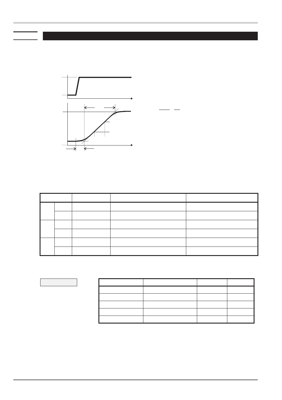
The optimization aid should be used with units on which the control parameters shall be set without self-tuning.
For this, the response of process variable x after a step change of correcting variable y can be used . Frequently, plot-
ting the complete response curve (0 to 100%) is not possible, because the process must be kept within defined limits.
Values T
g
and x
max
(step change from 0 to 100 %) or
Dt and Dx (partial step response) can be used to determine the
maximum rate of increase v
max
.
The control parameters can be determined from the values calculated for delay time T
u
, maximum rate of increase
v
max
, and characteristic K according to the formulas given below. Increase Pb1, if line-out to the setpoint oscillates.
Controlling
Manual tuning
46
KS 45
Tu
Tg
t
x
y
100%
0%
t
Yh
Xmax
{
X
{
t
y
= correcting variable
Y
h
= control range
Tu
= delay time (s)
Tg
= recovery time (s)
X
max
= maximum process value
V
max
=
Xmax
Tg
=
{
{
x
t
max. rate of increase of process value
Parameter adjustment effects
Parameter
Control
Line-out of disturbances
Start-up behaviour
Pb1 higher
increased damping slower line-out
slower reduction of duty cycle
lower
reduced damping
faster line-out
faster reduction of duty cycle
td1 higher
reduced damping
faster response to disturbances
faster reduction of duty cycle
lower
increased damping slower response to disturbances
slower reduction of duty cycle
ti1 higher
increased damping slower line-out
slower reduction of duty cycle
lower
reduced damping
faster line-out
faster reduction of duty cycle
Formulas
K = Vmax w Tu
controller behavior
Pb1 [phy.units]
td1 [s]
ti1 [s]
With 2-point and 3-point con-
trollers, the cycle time must be
adjusted to
t1 / t2 £ 0,25 * Tu
PID
1,7 w K
2 w Tu
2 w Tu
PD
0,5 w K
Tu
OFF
PI
2,6 w K
OFF
6 w Tu
P
K
OFF
OFF
3-point-stepping
1,7 w K
Tu
2 w Tu