7 limit value processing 27, 1 input value monitoring 27, Input value monitoring 27 – West Control Solutions KS 45 User Manual
Page 27: Limit 27 - 29, Limit value processing
6.7
Limit value processing
Max. three limit values can be configured for the outputs. Generally, each one of outputs
Out.1... Out.3 can be
used for limit value or alarm signalling.
Several signals allocated to an output are linked by a logic OR function.
6.7.1
Input value monitoring
g
The signal to be monitored can be selected separately for each alarm in the configuration. The following
signals are available:
•
Process value (display value)
•
Control deviation (process value - setpoint)
•
Control deviation with suppression at start up or setpoint modification
•
Measurement value INP1
•
Measurement value INP2 (option)
•
setpoint
•
Output value
g
* After switch-on or setpoint change, the alarm output is suppressed, until the process value is within the
limits for the first time.
If a time limit (
Src.x = 2) was configured, the alarm is activated after elapse of time 10 x ti1 (paramter
ti1 = integral time). ti1 switched off (ti1 = OFF) is considered as ¥ , i.e. the alarm activation is
omitted until the process value is within the limits once.
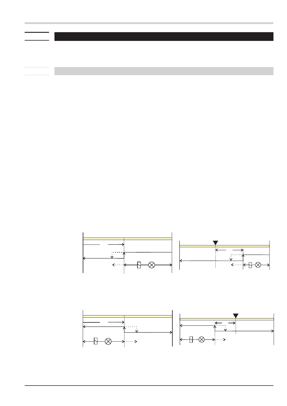
Each of the 3 limit values
Lim.1 … Lim.3 has 2 trigger points H.x (Max) and L.x (Min), which can be switched off
individually (parameter = “
OFF”). The hysteresis HYS.x of each limit value is adjustable.
Input value monitoring is as shown below:
Display range
Limit value 1
Outputs
Display range
Limit value 1
Outputs
Functions
Limit value processing
27
KS 45
H.1
LED rot / red
HYS.1
-1999
9999
H.1
operating principle with absolute alarm
L.1 = OFF
LED
HYS.1
H.1
-1999
9999
SP
operating principle with relative alarm
L.1 = OFF
L.1
LED
HYS.1
-1999
9999
SP
H.1 = OFF
L.1
HYS.1
-1999
9999
LED rot / red
L.1
H.1 = OFF