Electrical connections 11, 1 connecting diagram 11, 2 terminal connections 11 – West Control Solutions KS 45 User Manual
Page 11: Inp1 11, Connecting diagram 11, Terminal connections 11 - 12, 4 electrical connections, Connecting diagram, Terminal connections, 1 connecting the supply voltage
.
4
Electrical connections
4.1
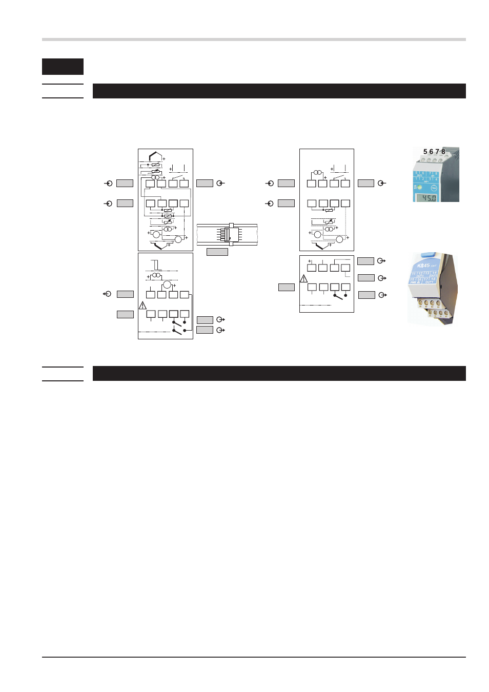
Connecting diagram
4.2
Terminal connections
a
Faulty connection might cause destruction of the instrument !
1 Connecting the supply voltage
Dependent on order
•
90 … 260 V AC
terminals: 15,16
•
24 V AC / DC
terminals: 15,16
For further information, see section
"Technical data"
g
Instruments with optional system interface:
Energization is via the bus connector of field bus coupler or power supply module. Terminals 15, 16 must
not be used.
2 Connecting input INP1
Input for the measurement value
a
resistance thermometer (Pt100/ Pt1000/ KTY/ ...), 3-wire connection
terminals: 1, 2, 3
b
resistance thermometer (Pt100/ Pt1000/ KTY/ ...), 4-wire connection
terminals: 2, 3, 5, 6
c
potentiometer
terminals: 1, 2, 3
d
current (0/4...20mA)
terminals: 2, 3
e
voltage (-2,5...115/-25...1150/-25...90/ -500...500mV)
terminals: 1, 2
f
voltage (0/2...10V/-10...10V/ -5...5V)
terminals: 2, 4
g
thermocouple
terminals: 1, 3
Electrical connections
KS 45
11
Connecting diagram
V
mV
INP2
INP1
OUT3
di1
8
7
6
3
2
1
5
3
4
(mV)
Data A
Data A
Data B
Data B
RGND
RGND
RS 485
KS45-1xY-xxxxx-xxx
Y
= 0, 1, 2, 3
V
14
13
12
16
15
11
mV
17 18
INP2
INP1
PWR
L
N
OUT1
OUT2
90...260V AC
24V AC/DC
di1
8
7
6
3
2
1
5
3
4
KS45-1xY-xxxxx-xxx
Y
= 4, 5
AC / DC
24VDC
top
1
5
2
7
a
b
c
d
e
a
b
c
d
e
f
g
14
13
12
16
15
11
17 18
OUT3
PWR
L
N
OUT1
OUT2
90...260V AC
24V AC/DC
4
Logic
V
h
i
j
k
6
3
2
1
3
1 2 3 4
1 2 3 4
8
9
0
11 12 13 14
11 12 13 14
15 16 17 18
15 16 17 18
a
b
a
b