Additional input inp2, Control input di1 – West Control Solutions KS 45 User Manual
Page 70
Heating current measurement
(via current transformer)
Input resistance:
approx. 49
W
Measurement span:
0...50 mA AC
Scaling:
freely selectable –1,999...9,999 A
ADDITIONAL INPUT INP2
(UNIVERSAL, OPTION)
Resolution:
>14 bits
Digital input filter:
adjustable 0.0...9,999 s
Scanning cycle:
100 ms
Linearization:
as for INP1
Measurement value correcti-
on:
2-point or offset
Type:
single-ended, exept
thermocouples
Thermocouples (Table 1)
Cold-junction compensation
• internal,
- additional error:
typ.:
max.:
ß_ 0,5 K
ß -2,5 K
• external,
- constant setting
0...100 °C
Remaining technical data as for INP1
Resistance thermometer
(Table 2)
Connection technology:
3-wire,
Remaining technical data as for INP1
Resistance measuring range
Remaining technical data as for INP1
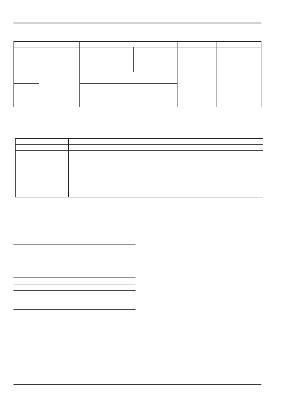
Current and voltage measuring ranges
(Table 3)
Remaining technical data as for INP1 except
• Voltage input ranges -10/0...10V, -5...5V are not possible.
• Millivolt input ranges: high-impedance input for low-impedance
sources
CONTROL INPUT DI1
Configurable as direct or inverse switch or push button!
Contact input
Connection of potential-free contact that is suitable for switching
‘dry’ circuits.
Technical data
70
KS 45
measuring range
inpur resistance
error
typ. resolution (Ô)
0...20 mA
20 [ (voltage demand ß 2,5 V)
£ 0,1 %
1,5 úA
0...10 Volt
~ 110 k [
£ 0,1 %
0,6 mV
-10...10 Volt
~ 110 k [
£ 0,1 %
1,2 mV
-5...5Volt
~ 110 k [
£ 0,1 %
0,6 mV
-2,5...115 mV*
? 1M[
£ 0,1 %
6 µV
-25...1150 mV*
? 1M[
£ 0,1 %
60 µV
-25...90 mV*
? 1M[
£ 0,1 %
8 µV
-500...500 mV*
? 1M[
£ 0,1 %
80 µV
-200...200 mV*
? 1M[
£ 0,1 %
420 µV
* for INP1: high-impedance, without break monitoring
for INP2: high-impedance, break monitoring always active
Table 3: Current and voltage input
type
measuring current
measuring range
error
typ. resolution (Ô)
Pt100***
ß 0,25 mA
-200...100 (150) °C
-328...212°F
ß 1 K
0,1 K
0,1 K
0,1 K
Pt100
-200...850°C
-328...1562°F
ß 1 K
Pt1000
-200...850°C
-328...1562°F
ß 2 K
KTY 11-6*
-50...150°C
-58...302°F
ß 2 K
0,1 K
special
*
0...4500 [**
Я 0,1 %
Я 0,1 %
Я 0,1 %
Я 0,1 %
Я 0,1 %
0,01 %
0,01 %
0,01 %
0,01 %
0,01 %
special
0...450 [**
Poti
0...160 [**
Poti
0...450 [**
Poti
0...1600 [**
Poti
0...4500 [**
* Default setting is the characteristic for KTY 11-6 (-50...150°C)
** Including lead resistance
*** up to 150°C at reduced lead resistance
Table 2: Resistive inputs