Technical data 69, 15 technical data, Inputs universal input inp1 – West Control Solutions KS 45 User Manual
Page 69: Additional input inp2 (current)
.
15
Technical data
INPUTS
UNIVERSAL INPUT INP1
Resolution:
>14 bits
Decimal point:
0 to 3 decimals
Digital input filter:
adjustable 0.0...9,999 s
Scanning cycle:
100 ms
Linearization:
15 segments, adaptable with BlueControl®
Measurement value
correction:
2-point or offset
Type:
single-ended (except for thermocouples)
Thermocouples (Table 1)
Input resistance:
³1 MW
Influence of source resistance:
1 µV/
W
Input circuit monitor:
sensor break, polarity
Cold-junction compensation
• internal
Typical additional error:
ß _ 0.5 K (ß 1.2 K max)
• external
- constant reference
0...100 °C
Break monitoring
Sensor current:
ß1 µA
Operating sense:
configurable
Resistance thermometer (Table 2)
Connection technology:
3 -wire, 4-wire (not at INP2-usage)
Lead resistance:
max. 30
W (for max. end of span)
Input circuit monitoring: break and short circuit
Measurement span
The BlueControl® software enables the internal characteristic
curve for the KTY 11-6 temperature sensor to be adapted.
Physical measurement range:
0...4,500
W
Current and voltage measurement (
Table 3)
Span start and span: anywhere within the measurement range
Scaling:
freely selectable, –1,999...9,999
Input circuit
12,5% below span from 4...20mA / 2...10V
Monitoring (current): start (2 mA)
O
2
measuring (option)
EMI measuring by means of INP1 (high-impedance mV inputs)
suitable for probes with
• constant sensor temperature (heated probes), setting by means
of parameter
• measured sensor temperature (non-heated probes),
measurement by means of INP2
ADDITIONAL INPUT INP2 (CURRENT)
Resolution:
>14 bits
Digital input filter:
adjustable 0.0...9,999 s
Scanning cycle:
100 ms
Linearization:
as for INP1
Measurement value correction:
2-point or offset
Type:
single-ended
Current measurement
Input resistance:
approx. 49
W
Span start and span:
anywhere between 0 and 20 mA
Scaling:
freely selectable –1,999...9,999
Input circuit monitoring:
12,5% below span start (2 mA)
Technical data
KS 45
69
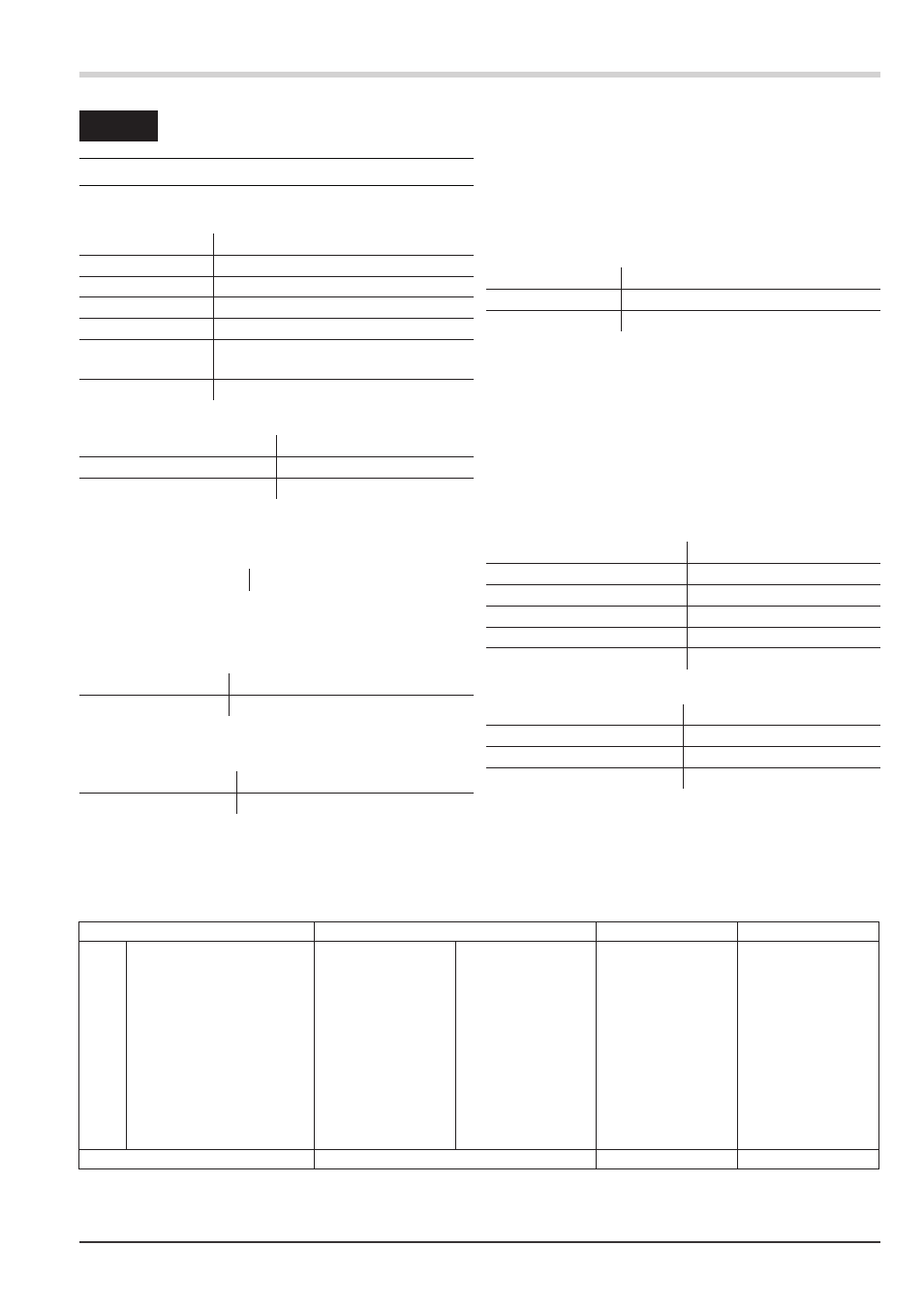
thermocouple type
measuring range
error
typ. resolution (Ô)
L
Fe-CuNi (DIN)
-100...900°C
-148...1652°F
ß 2 K
0,1 K
J
Fe-CuNi
-100...1200°C
-148...2192°F
ß 2 K
0,1 K
K
NiCr-Ni
-100...1350°C
-148...2462°F
ß 2 K
0,2 K
N
Nicrosil/Nisil
-100...1300°C
-148...2372°F
ß 2 K
0,2 K
S
PtRh-Pt 10%
0...1760°C
32...3200°F
ß 2 K
0,2 K
R
PtRh-Pt 13%
0...1760°C
32...3200°F
ß 2 K
0,2 K
T**
Cu-CuNi
-200...400°C
-328...752°F
ß 2 K
0,05 K
C
W5%Re-W26%Re
0...2315°C
32...4199°F
ß 3 K
0,4 K
D
W3%Re-W25%Re
0...2315°C
32...4199°F
ß 3 K
0,4 K
E
NiCr-CuNi
-100...1000°C
-148...1832°F
ß 2 K
0,1 K
B*
PtRh-Pt6%
0(100)...1820°C
32(212)...3308°F
ß 3 K
0,4 K
special
-25....75 mV
ß 0,1 %
0,01 %
* Values for type B apply from 400°C upwards
**Values apply from -80°C upwards
Table 1 Thermocouple measurement ranges