Electrical connections – KROHNE OPTIBAR PC 5060 C EN User Manual
Page 35
ELECTRICAL CONNECTIONS
4
35
OPTIBAR PC 5060 C
www.krohne.com
04/2014 - 4003437201 - MA OPTIBAR PC 5060 C R01 en
4.3.2 Connection in the housing base (external housing)
Procedure
• Unscrew the housing cover
• If present, remove the display and adjustment module by turning it to the left
• Loosen union nut of the cable gland
• For preparation of connection cable refer to
Cable preparation on page 30
• Push the cable through the cable gland into the terminal compartment
• Insert the wire ends into the open terminals according to the wiring plan. Solid cores as well
as flexible cores with cable end sleeves can be inserted directly into the terminal openings. In
case of flexible cores, press the spring terminal with a small screwdriver to open the terminal
opening.
• Check the hold of the wires in the terminals by lightly pulling on them
• Connect the cable shield to the internal ground terminal, connect the outer ground terminal to
the equipotential bonding
• Tighten the union nut of the cable gland. The sealing ring must completely enclose the cable
• Screw the housing cover back on
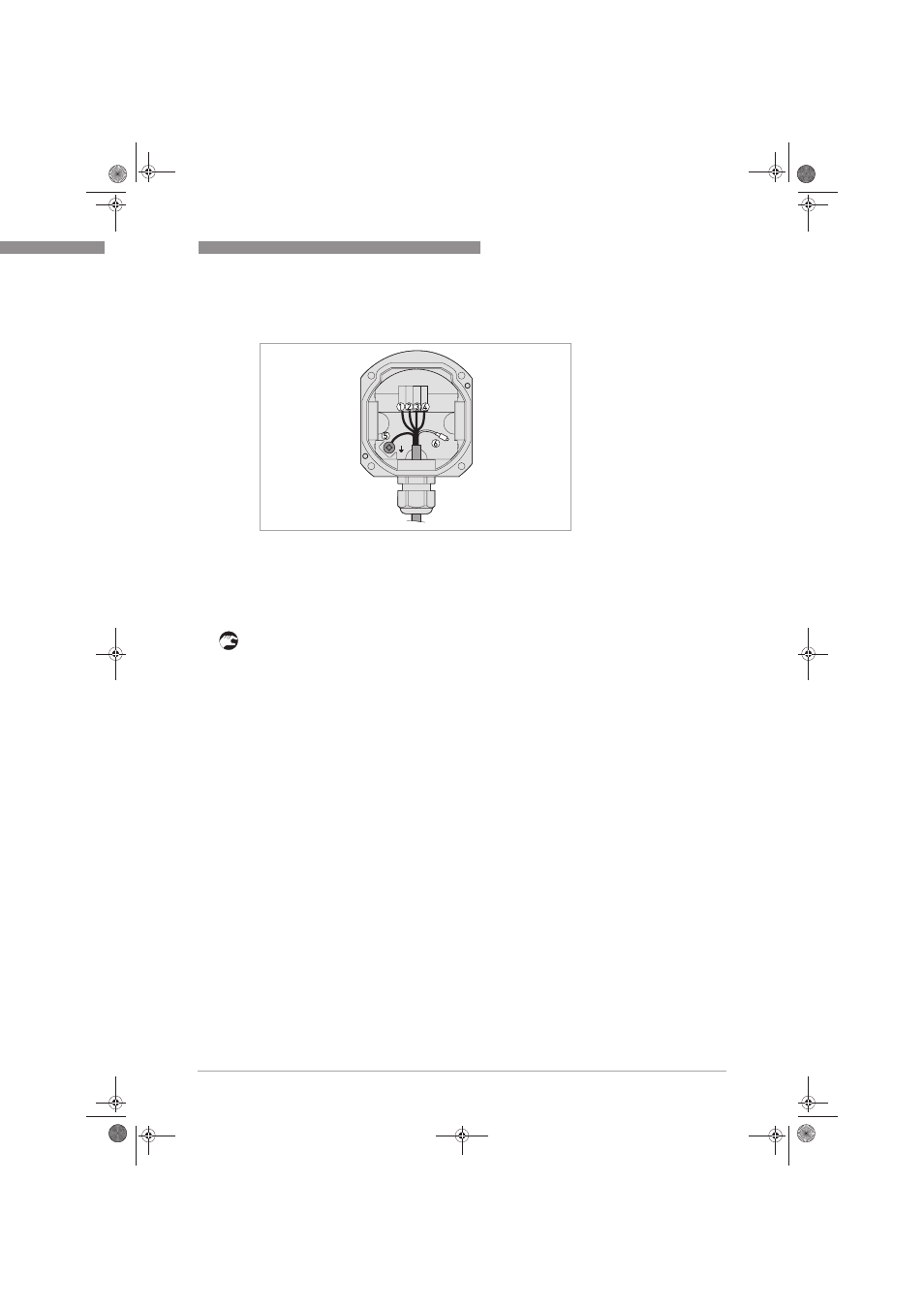
Figure 4-8: Terminal box from front
1 Brown
2 Blue
3 Yellow
4 White
5 Shielding
6 Pressure equalisation capillary
.book Page 35 Friday, May 2, 2014 12:49 PM