Operation – KROHNE GFC 300 FOUNDATION FIELDBUS User Manual
Page 49
OPERATION
4
49
GFC 300
www.krohne.com
07/2012 - 4001866001 - AD GFC 300 FF R01 en
PRIMARY_VALUE_
PRIMARY_VALUE_
PRIMARY_VALUE_
PRIMARY_VALUE_
302
302
302
302
Gain
Gain
Gain
Gain
The measured gain value and status available to the Function
Block.
-
STATUS
Status
R
Digital transducers, unlike their analogue versions, can detect
faults that make the measurement bad or prevent the
actuator from responding. This additional, valuable
information will be passed along with each transmission of a
data value in the form of a status attribute.
-
VALUE
Value
R
A numerical quantity entered by a user or calculated by the
algorithm.
-
PRIMARY_VALUE_
PRIMARY_VALUE_
PRIMARY_VALUE_
PRIMARY_VALUE_
RANGE_302
RANGE_302
RANGE_302
RANGE_302
corrected volume
corrected volume
corrected volume
corrected volume
flow range
flow range
flow range
flow range
The high and low range limit values, the engineering units
code and the number of digits to the right of the decimal point
to be used to display the Primary Value.
-
EU_100
Engineering Unit
100
R
The engineering unit value which represents the upper end of
range of the associated Block Parameter.
120.0
EU_0
Engineering Unit 0
R
The engineering unit value which represents the lower end of
range of the associated Block Parameter.
0.0
UNITS_INDEX
Units Index
R/W
Device Description units code index for the engineering unit
descriptor for the associated block value.
dB
Settings:
dB
DECIMAL
Decimal (Point)
R
The number of digits to the right of the decimal point which
should be used by an interface device in displaying the
specified parameter.
2
PRIMARY_VALUE_
PRIMARY_VALUE_
PRIMARY_VALUE_
PRIMARY_VALUE_
303
303
303
303
SNR
SNR
SNR
SNR
The measured SNR value and status available to the Function
Block.
-
STATUS
Status
R
Digital transducers, unlike their analogue versions, can detect
faults that make the measurement bad or prevent the
actuator from responding. This additional, valuable
information will be passed along with each transmission of a
data value in the form of a status attribute.
-
VALUE
Value
R
A numerical quantity entered by a user or calculated by the
algorithm.
-
PRIMARY_VALUE_
PRIMARY_VALUE_
PRIMARY_VALUE_
PRIMARY_VALUE_
RANGE_303
RANGE_303
RANGE_303
RANGE_303
SNR range
SNR range
SNR range
SNR range
The high and low range limit values, the engineering units
code and the number of digits to the right of the decimal point
to be used to display the Primary Value.
-
EU_100
Engineering Unit
100
R
The engineering unit value which represents the upper end of
range of the associated Block Parameter.
120.0
EU_0
Engineering Unit 0
R
The engineering unit value which represents the lower end of
range of the associated Block Parameter.
0.0
UNITS_INDEX
Units Index
R/W
Device Description units code index for the engineering unit
descriptor for the associated block value.
dB
Settings:
dB
DECIMAL
Decimal (Point)
R
The number of digits to the right of the decimal point which
should be used by an interface device in displaying the
specified parameter.
2
PRIMARY_VALUE_
PRIMARY_VALUE_
PRIMARY_VALUE_
PRIMARY_VALUE_
304
304
304
304
velocity of sound 1
velocity of sound 1
velocity of sound 1
velocity of sound 1
The measured velocity of sound 1 value and status available to
the Function Block.
-
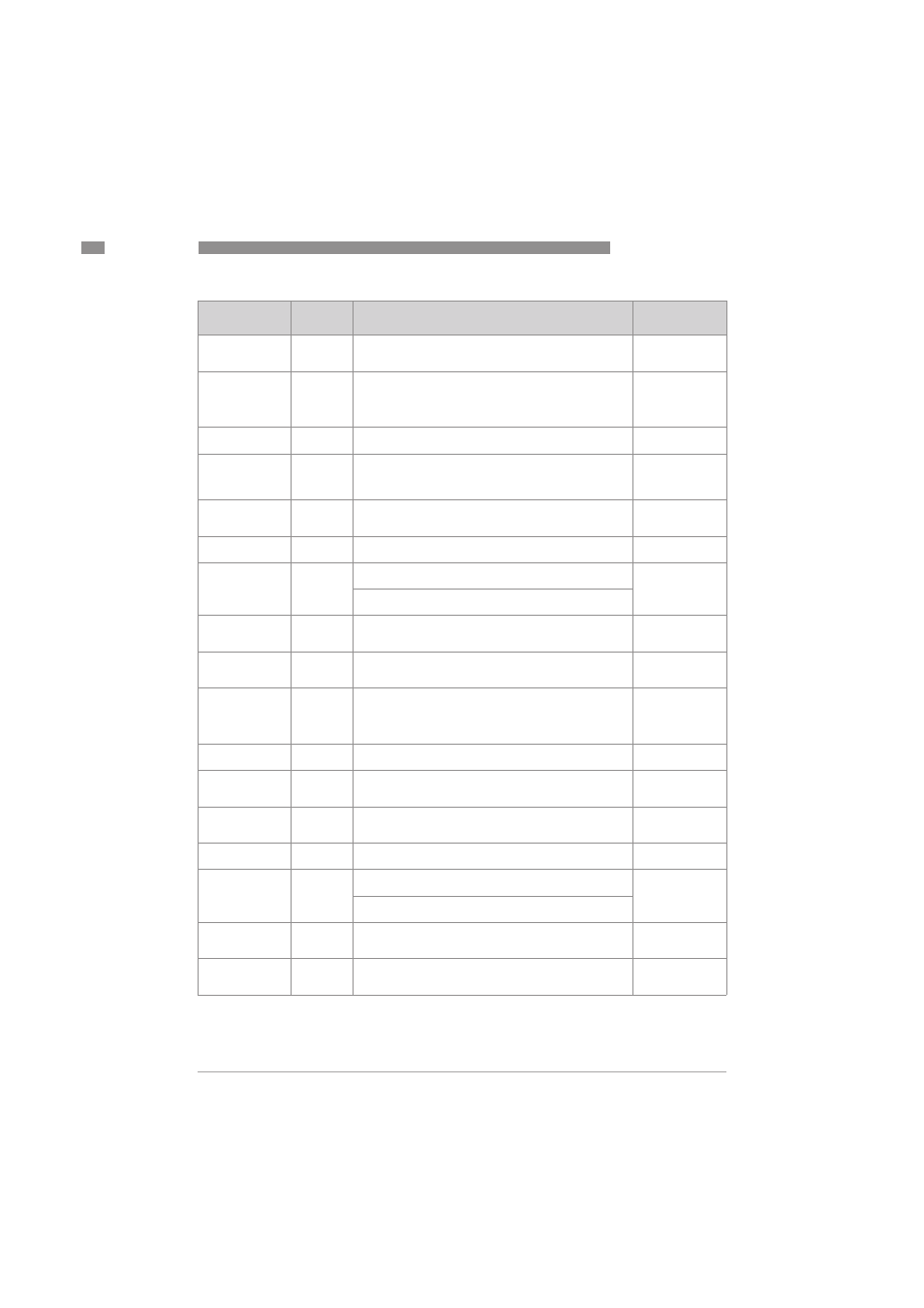
Parameter
Parameter
Parameter
Parameter
DD name
Access
Description and settings
Initial Value