Load / remote sensing wire selection, Load configuration – GW Instek PSH-A Series 360W User Manual User Manual
Page 13
Setup
25
Load / Remote Sensing Wire Selection
The following instructions apply to both load wire and remote
sensing wire, unless noted.
Wire size (FOR
LOAD ONLY)
Load wires must have enough current capacity
to minimize cable loss and load line impedance.
Voltage drop across a wire should not excess
0.5V. The following list is the wire current rating
at 450A/cm
2
.
Wire size
(AWG)
Max.
current (A)
Wire size
(AWG)
Max.
current (A)
20 2.5 6 61
18 4 4 97
16 6 2 155
14 10 1 192
12 16 1/0
247
10 21 2/0
303
8 36
Wire length
To avoid excessive cable loss, shorten the
distance between PSH and load as much as
possible. Remote sensing compensates cable
loss up to 0.5V.
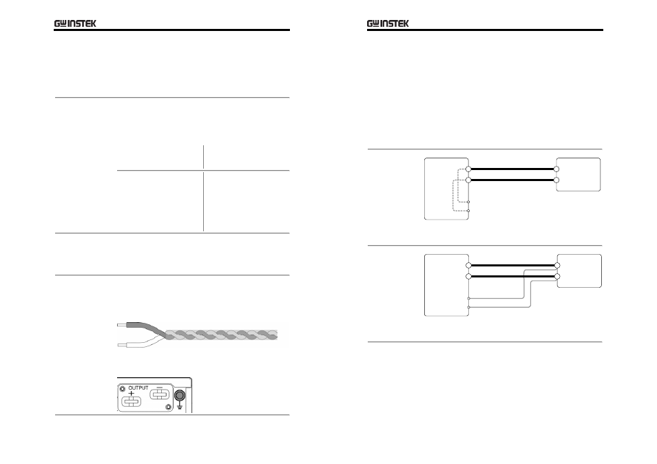
Wire shielding
To minimize noise effect and load line
impedance, use shielded pair wiring. Twisted
wires are more effective, especially for remote
sensing.
Wire shield should be connected to the rear
panel ground connector.
PSH
User
Manual
26
Load Configuration
Select the appropriate configuration for the target application.
For local sensing and remote sensing explanation, see the
previous page.
For connection guideline, see page25 (wire selection), page30 (load
connection), page32 (remote sensing connection).
Single PSH + single load
Single Load +
Local Sensing
PSH
—OUT
+OUT
—IN
+IN
Load
—Sense
+Sense
Connect the output wire to the load and the sense
terminal to the PSH local output monitor.
Single Load +
Remote
Sensing
PSH
+OUT
+IN
Load
+Sense
—IN
—OUT
—Sense
Connect both the output wire and the remote
sensing wire to the load.