A2.4 setting the di function blocks, A2.4, A-19 – Yokogawa Multi Channel Oxygen Analyzer System ZR22/AV550G User Manual
Page 68
A-19
IM 11M12D01-61E
If simulation is enabled, AI block uses SIMULATE Status and SIMULATE Value as the input, and if
disabled, the AI block uses Transducer Status and Transducer Value as input. Refer to Section 6.3,
“Simulation Function.”
A2.4 Setting the DI Function Blocks
DI function blocks output switch signals received from the transducer block.
Two DI blocks (DI1 and DI2) in each AV550G have independent parameters. Set up the parameters
of each AI block you use, individually as necessary. The following shows the DI setting procedure as
an example.
(1) Setting the channel
The CHANNEL parameter of the DI block, which specifies the switch number of the transducer’s
switch to be input to DI (DI1: 4, DI2: 5) for a AV550G.
(2) Setting the damping time constant
Access the PV_FTIME parameter and set the damping time constant (in units of seconds).
(3) Simulation
Perform simulation of each AI function block by setting the desired value and status of the input to the
block. Access the SIMULATE_D parameter and change the values of its elements as follows.
The DI block uses SIMULATE_D Status and SIMULATE_D Value in the SIMULATE_D parameter
as its input status and value when simulation is active, or uses Transducer Status and Transducer
Value in SIMULATE_D as its input status and value when simulation is disabled. Refer to Section 6.3,
“Simulation.”
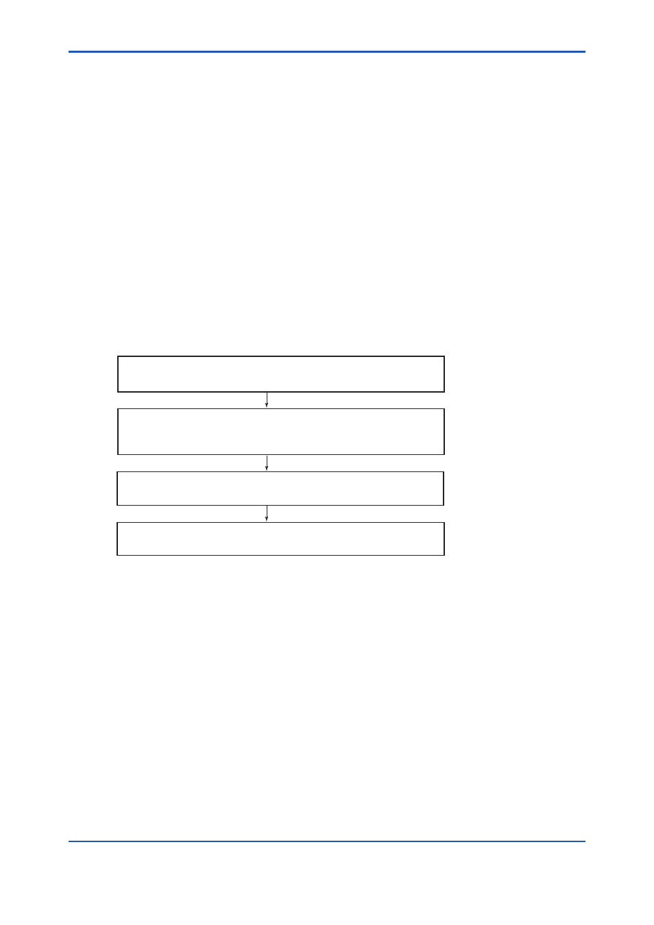
FA0212.ai
Access the SIMULATE_D Value element and set the desired
input value.
Access the SIMULATE_D Status element and set the desired
status code.
Change value of the En/Disable element of SIMULATE_D.
1: Disabled
2: Active
REMOTE LOOP TEST SWITCH is written to SIM_ENABLE_MSG
(index 1044) parameter of the resource block.