Yokogawa Multi Channel Oxygen Analyzer System ZR22/AV550G User Manual
Page 22
<5. CONFIGURATION>
5-3
IM 11M12D01-61E
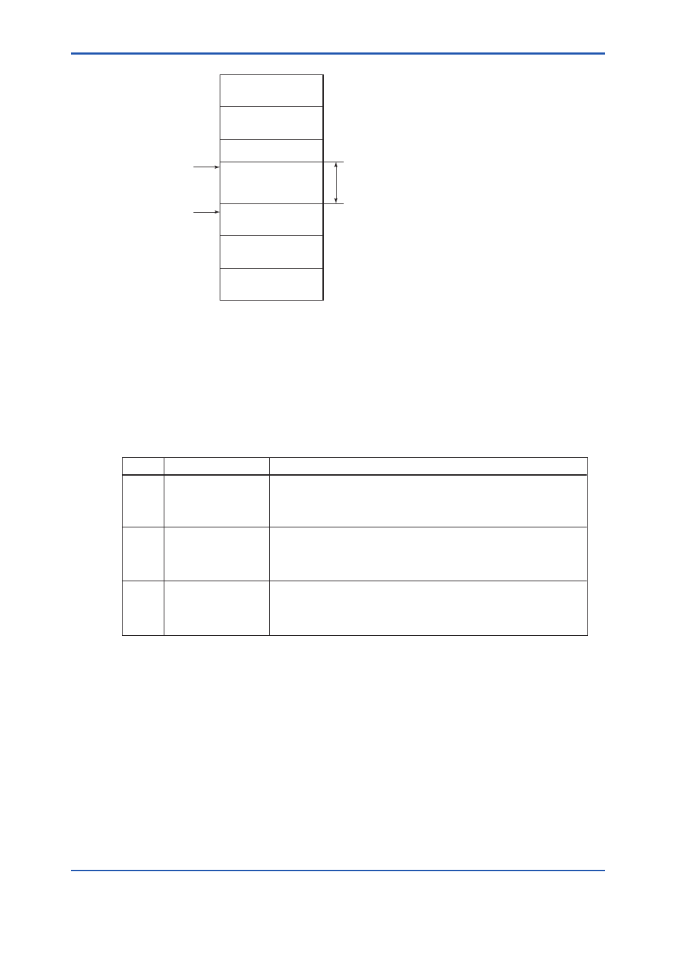
Figure 5.1 Available Range of Node Addresses
For all Link Master (LM) devices, the parameters listed in Table 5.2 are set to ensure stable operation.
These parameters determine the time each LM device waits for a response, and are set so as to allow
sufficient for the slowest device on the Fieldbus to respond. (The values of these parameters for each
connected Fieldbus device is defined in its capability file (CFF). A LM host may check CFF files of
connected Fieldbus devices and set these parameters automatically).
Table 5.2 Operation Parameter Values of AV550G to be Set to LM Device
Bridge device
Unused
0x10
0x0F
0x00
0x14
0x13
0xF7
0xF8
0xFB
0xFC
0xFF
V(FUN)
V(FUN)+V(NUN)
LM devices
Unused
V(NUN)
Basic devices
Default addresses
Portable device addresses
F0501.ai
Time interval required to send a message, expressed as a multiple of
V(SlotTime), the time (256μS) required to send one octet.
For the AV550G, the value is 4. Set this to the max. value among
connected devices.
T0502.ai
Symbol
Parameter name
Description and value
V (ST)
Slot-Time
V (MID) Minimum-Inter-PDU-
Delay
Min. value of interval between messages, expressed as a multiple of
V(SlotTime), the time (256μS) required to send one octet.
For the AV550G, the value is 4. Set this to the max. value among
connected devices.
V (MRD) Maximum-Response-
Delay x Slot-time
Represents the time a LM should wait for a device to respond.
For the AV550G, the value is 12. (Since V(ST) is predefined, the
value of this product determines V(MRD)). Set this to the max. value
among connected devices.
x V (ST)