Yokogawa AXFA14G/C User Manual
Page 62
IM 01E20F12-01E
9-4
9. PARAMETER LISTS
T0902-2.EPS
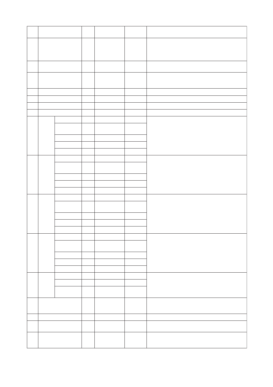
Index
Parameter
Valid Range
Initial Value
Description
Write
Mode
33
FSAFE_TYPE
Defines reaction of device, if a fault is detected.
Auto
0: Failsafe Value
1: Last Valid OUT
Value
2: Wrong Calculated
Value
0.0 to 50.0% of
range
1: Last Valid
OUT
Value
34
FSAFE_VALUE
Default value for the OUT parameter, if sensor or sensor electronic
fault is detected. The unit of this parameter is the same like the OUT one.
Auto
0.0
35
ALARM_HYS
Amount the PV must return within the alarm limits before the alarm
condition clears. Alarm Hysteresis is expressed as engineering units
of the PV span.
Auto
0.5% of range
max. Value
37
HI_HI_LIM
The setting for high high alarm in engineering units.
Auto
+INF
max. Value
39
HI_LIM
The setting for high alarm in engineering units.
Auto
+INF
min. Value
41
LO_LIM
The setting of the low alarm in engineering units.
Auto
-INF
min. Value
0: No alarm
Alarm active exclude 0
43
LO_LO_LIM
The setting of the low low alarm in engineering units.
Auto
-INF
46
This parameter is used in order to show the state of the upper limit of
alarms. This parameter contains the state of the upper limit of an
alarm and the related time stamp. The time stamp expresses the
time the measured variable has been equal or higher than the upper
limit of the alarm.
–
0
Unacknowledged
–
0
Alarm State
–
0
Time_Stamp
–
0
Subcode
–
0
Value
0: No alarm
Alarm active exclude 0
–
0
Alarm State
–
0
Time_Stamp
–
0
Subcode
–
0
Value
HI_HI_
ALM
(DS-39)
47
This parameter is used in order to show the state of the upper limit of
warnings. This parameter contains the state of the upper limit of a
warning and the related time stamp. The time stamp expresses the
time the measured variable has been equal or higher than the upper
limit of the warning.
–
0
Unacknowledged
HI_ALM
(DS-39)
0: No alarm
Alarm active exclude 0
–
0
Alarm State
–
0
Time_Stamp
–
0
Subcode
–
0
Value
This parameter is used in order to display the span velocity
corresponding to PV_SCALE.EU100 (EU0).
–
0
Unacknowledged
VELOCITY_CHECK
0: No alarm
Alarm active exclude 0
0: Disabled,
Enable exclude 0
–
0
Alarm State
–
0
Time_Stamp
–
0
Subcode
–
0
Value
49
This parameter is used in order to show the state of the lower limit of
alarms. This parameter contains the state of the lower limit of an
alarm and the related time stamp. The time stamp expresses the
time the measured variable has been equal or lower than the lower
limit of the alarm.
–
0
Unacknowledged
LO_LO_
ALM
(DS-39)
48
This parameter is used in order to show the state of the lower limit of
warnings. This parameter contains the state of the lower limit of a
warning and the related time stamp. The time stamp expresses the
time the measured variable has been equal or lower than the lower
limit of the warning.
LO_ALM
(DS-39)
50
For commissioning and test purposes the input value from the
Transducer Block in the Analog Input Function Block AI-FB can be
modified. That means that the Transducer and AI-FB will be
disconnected.
Auto
0
Simulate_Status
Auto
0
Simulate_Value
Auto
Auto
0: Disabled
Simulate_Enabled
SIMULATE
(DS-50)
Character
0 to 99.999
51
61
View objects allow the following groups of physical block parameter
values to be read with one read request.
ST_REV, MODE_BLK, ALARM_SUM, OUT
–
VIEW_ANALOG_INPUT_FB
62
If a specific unit of OUT parameter is not in the code list the user has
the possibility to write the specific text in this parameter. The unit
code is then equal “textual unit definition”.
OUT_UNIT_TEXT
52-60 reserved by PNO