Yokogawa AXFA14G/C User Manual
Page 23
IM 01E20F12-01E
4-9
4. CONFIGURATION
CHANNEL:
This is the parameter to specify the value of the
transducer block to be input to the DI block. Each DI
block is assigned to either “High Limit”, “Low Limit”,
“Adhesion Alarm” or “Adhesion Warning”.
This parameter enables to select among
“LIMSW_1_VALUE_D”, “LIMSW_2_VALUE_D”,
“SWITCH_1_VALUE_D” and
“SWITCH_2_VALUE_D”.
Also it enables to set “High/Low Limit” or “Adhesion
Alarm/Warning” in each DI block.
INVERT:
This is the parameter which indicates whether the input
value from the transducer block should be logically
inverted before it is stored in the OUT_D.
0: Not inverted
1:invert
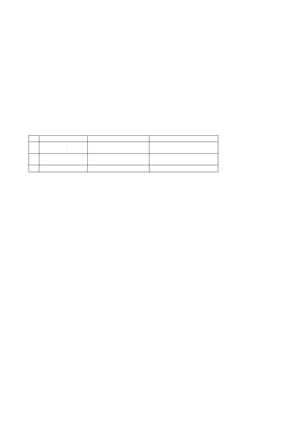
FSAFE_TYPE:
This is the parameter which defines the operation of the function block if a fault is detected.
Table 4.7
FSAFE_TYPE
1
0: FSAFE_VAL
2
1: last valid OUT Value
3
2: wrong calculated Val
UNCERTAIN_Substitude Value
UNCERTAIN_LastUsable Value
Bad:* (* as calculated)
The status is shown in Table 4.8
FSAFE_VAL is used as OUT_D.
If there is no valid value available,
then UNCERTAIN- Inital_Value.
Value
Status
Remark
T0408.EPS
FSAFE_VAL_D:
This is the parameter which sets the default value for
the OUT_D parameter, if sensor or sensor electric fault
is detected.