4 bus and axf power on, Bus and axf power on -3 – Yokogawa AXFA14G/C User Manual
Page 10
IM 01E20F12-01E
3-3
3. GETTING STARTED
3.4 Bus and AXF Power ON
Address setting Switch
A setup of bus address is possible by the change with a
parameter, or the hardware slide switch.
The set address which is done by hardware is higher
priority than by software.
Following description is how to set the bus address
using by hardware slide switch.
Refer to section 5.3 when the bus address is set by software.
The AXF must turn off the power supply when the bus
address is changed by hardware slide switch.
The device information, including Tag Desc., Bus
address, and Ident Number, is described on the sheet
attached to the AXF. The device information is given
in duplicate on this sheet.
Confirm the bus address written in the device information.
The default bus address is set as 126 (hexadecimal 7E) at the
factory unless otherwise specified when ordered.
F0302.EPS
: 0x070D (=1805)
:
:
:
:
:
Note:
PROFIBUS DEVICE INFORMATION
Device Serial Number
Tag Desc.
Bus Address
Serial Number
Physical Location
Ident Number
DTM, EDD and GSD files are available on the following YOKOGAWA website:
http://www.yokogawa.com/fld/doc/profibus/
DTM, EDD and GSD files are available on the following YOKOGAWA website:
http://www.yokogawa.com/fld/doc/profibus/
: 0x070D (=1805)
:
:
:
:
:
Note:
PROFIBUS DEVICE INFORMATION
Device Serial Number
Tag Desc.
Bus Address
Serial Number
Physical Location
Ident Number
Figure 3.2 Device Information Sheet Attached to AXF
Confirm that the AXF is turned off before opening the front cover.
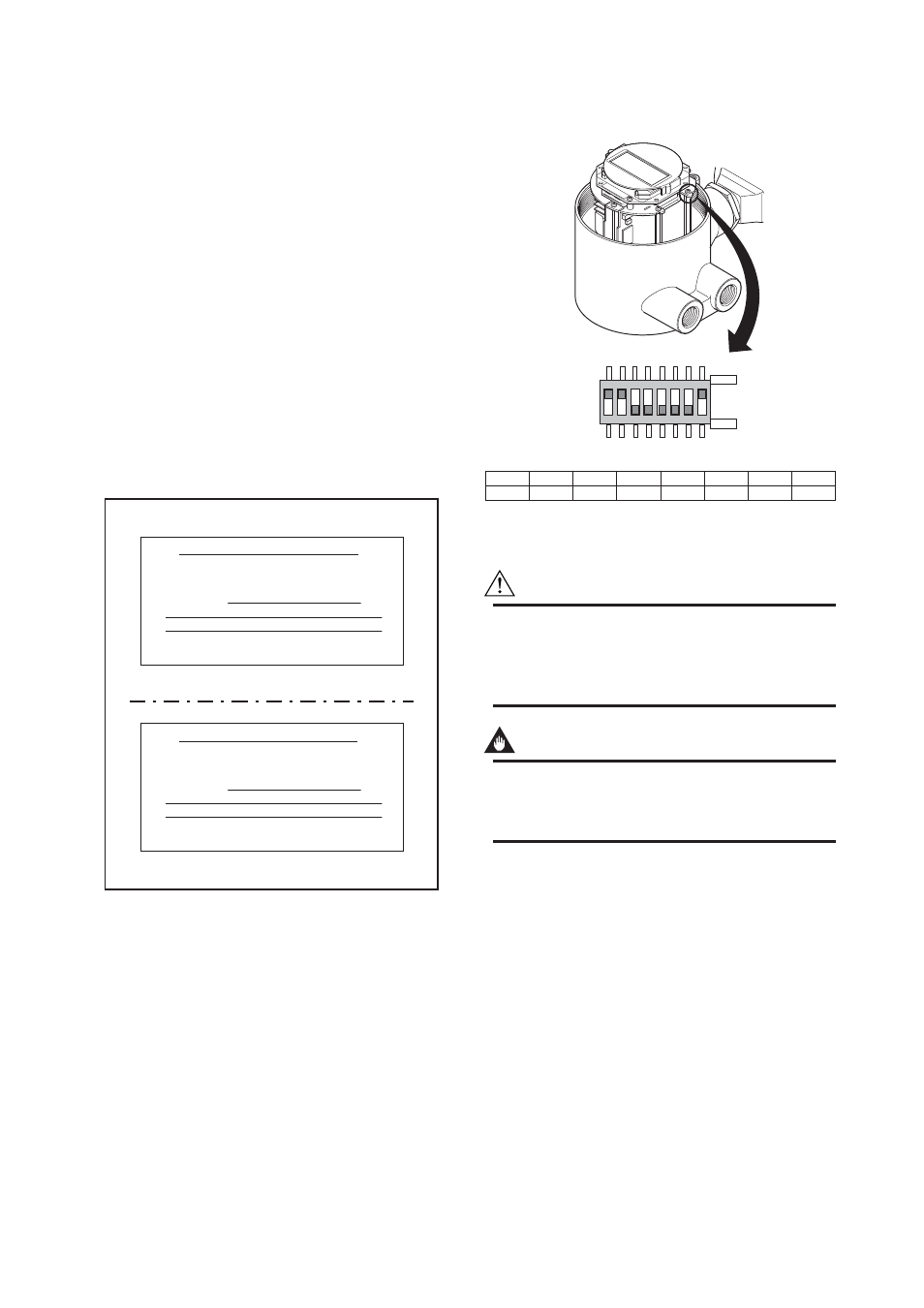
The bus address switch is located as shown in figure 3.3.
The No. 8 switch of SW102 is turned ON first. Other
seven switches of No. 1 to No. 7 on the SW102 are for
setting address. No. 1 switch of SW102 is allocated for
bit0 of address, and No. 7 switch of SW102 is allo-
cated for bit6 of address. The setting condition of the
SW102 as shown in figure 3.3 is 3 as the set bus
address number as an example.
If two or more AXFs are connected on the same bus,
each AXF must be set as different bus address.
The front cover must be closed after finish the work of
the bus address setting.
8
7
6
5
4
3
2
1
ON
OFF
OFF
OFF
OFF
OFF
ON
ON
ADDRESS
MSB
LSB
O
N
1
2
3
4
5
6
7
8
OFF
ON
SW102
F0303E.EPS
Figure 3.3 Address Switch
WARNING
When opening the cover, wait for more than 10
minutes after turning off the power. Furthermore,
opening of the cover must also be carried out by the
trained personnel having knowledge of safety standard.
IMPORTANT
To preserve the safety, do not touch the electri-
cal circuit and the cables except the Bus ad-
dress switch.
Bus and AXF Power ON
Firstly, turn on the power of the host, and then, the bus
and also the power for the AXF. Where the AXF is
equipped with the LCD indicator, first all segments are
lit, then the display begins to operate.
Using the host device display function, check that the
AXF is in operation on the bus.
If no AXF is detected, check the available address
range. If the Bus address and Tag Desc. are not
specified when ordering, default value is factory set. If
two or more AXFs are connected at the same time with
default value, only one AXF will be detected from the
host as AXFs have the same initial address. Separately
connect each AXF and set a different address for each.