2 ai block parameter list (slot 1), Ai block parameter list (slot 1) -3 – Yokogawa AXFA14G/C User Manual
Page 61
IM 01E20F12-01E
9-3
9. PARAMETER LISTS
9.2
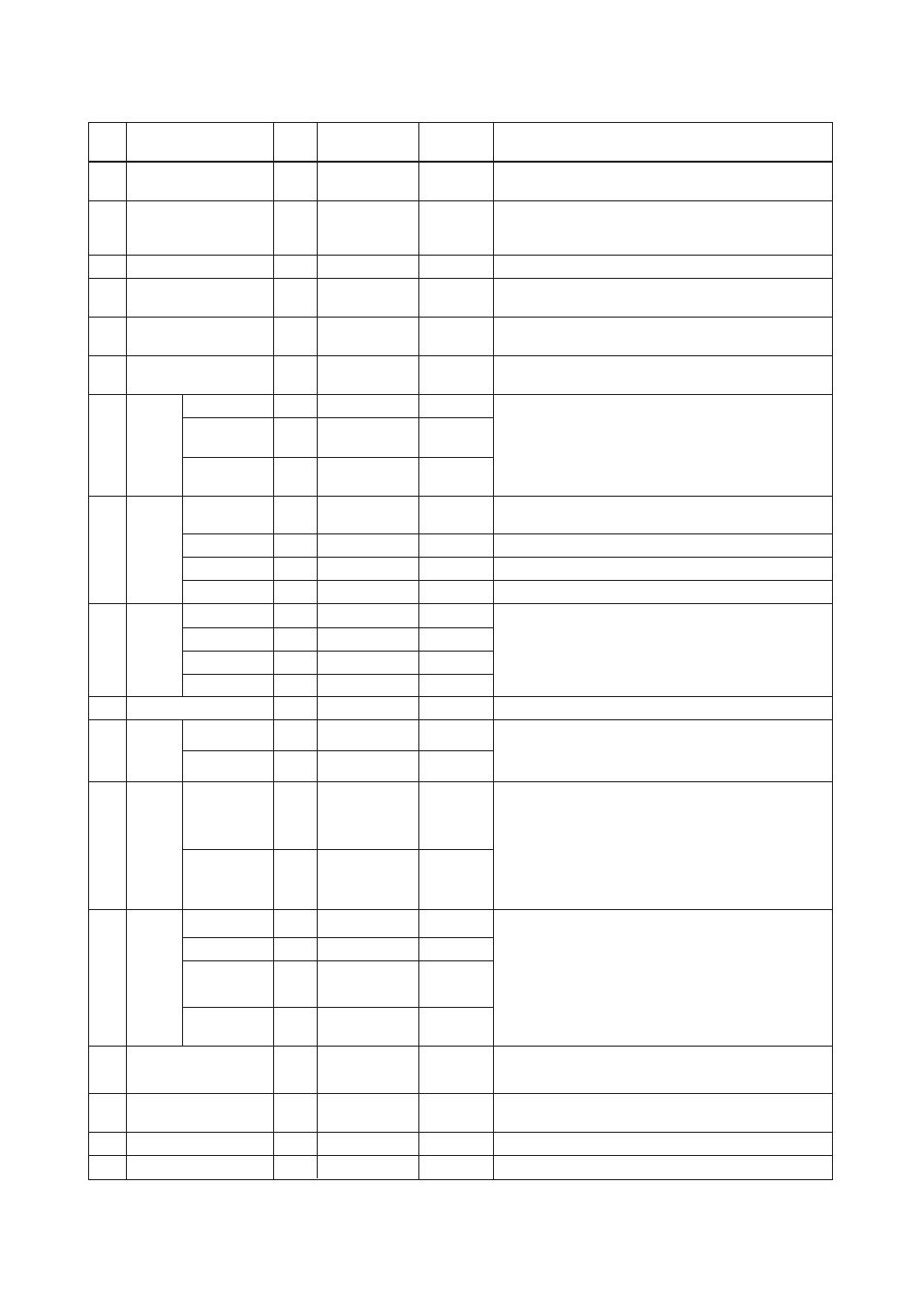
AI Block Parameter List (Slot 1)
T0902-1.EPS
Index
Parameter
Valid Range
Initial Value
Description
Write
Mode
Information on this block such as Block Tag, DD Revision, Execution
Time etc.
The revision level of the static data associated with the function block.
The revision value will be incremented each time a static parameter
value in the block is changed.
The user description of the intended application of the block.
The strategy field can be used to identify grouping of blocks.
This data is not checked or processed by the block.
The identification number of the plant unit. This information may be
used in the host for sorting alarms, etc.
16
–
BLOCK_OBJECT
17
–
0
ST_REV
18
Auto
TAG_DESC
19
Auto
0
0 to 65535
STRATEGY
20
Auto
0
0 to 255
ALERT_KEY
Set the Target of block mode (MODE_BLK) to Auto or O/S according
to the Write Mode of the parameter to be set or changed.
The mode parameter is a structured parameter composed of the
actual mode, the normal mode and the permitted mode.
Actual: Indicates the current operating condition.
Permit: Indicates the operating condition that the block is allowed
to take.
Normal: Indicates the operating condition that the block will usually
take.
21
22
Auto
Auto
–
Actual
MODE_
BLK
(DS-37)
Auto
The current alert status, unacknowledged status, unreported status
and disabled status of the alarms associated with the function block.
23
–
Current
ALARM_
SUM
(DS-42)
24
BATCH
(DS-67)
25
Not used
0
for future use
–
Unacknowledged
0
for future use
–
Unreported
0
for future use
–
Disabled
0
This parameter is intended to be used in Batch applications in line
with IEC 61512.
Auto
BATCH_ID
0
26
OUT
(DS-33)
This parameter contains the current measurement value from
Transducer Block or configuration adjusted engineering unit and the
belonging state in AUTO MODE.
OUT contains the value and status set by an operator in MAN MODE.
Man
Value
0
27
PV_
SCALE
Conversion of the Process Variable into percent using the high and
low scale values.
The engineering unit of PV_SCALE high and low scale values are
direct related to the PRIMARY_VALUE_UNIT of the configured
Transducer Block (configured via Channel parameter).
The PV_SCALE high and low scale values follow the changes of the
PRIMARY_VALUE_UNIT of the related Transducer Block
automatically, i.e. a change of the Transducer Block PRIMARY_
VALUE_Unit causes no bump at OUT from AI.
O/S
0.00001 to 32000
or
0
0.00001 to 32000
or
0
Array 1
O/S
1342: %, 1355:Ml/d
1522: Ml/h
1521: Ml/min , etc
Array 2
Specified at the
time of order
29
LIN_TYPE
This parameter is used in order to select the type of linearization.
O/S
0: no
linearisation
250: Not used
251: None
0
28
OUT_
SCALE
(DS-68)
Scale of the Process Variable.
This parameter contains the values of the lower limit and upper limit
effective range, the code number of the engineering unit of Process
Variable and the number of digits on the right hand side of the
decimal point.
O/S
EU at 100%
O/S
EU at 0%
O/S
Units Index
Auto exclude
0, 1, 2, 3
O/S
Decimal Point
Specified at the
time of order
Specified at the
time of order
Man
Status
0
0
0
4
Auto
RUP
0
Auto
OPERATION
0
Auto
PHASE
0
–
Permitted
O/S, Man,
Auto
The permitted bit is
only available.
O/S bit, Man bit,
Auto bit
–
Normal
Auto
Permitted bit is
only available.
Bit1, 2, 3, 4, and
7 are available.
TARGET_MODE
30
CHANNEL
Reference to the active Transducer Block which provides the
measurement value to the Function Block.
31
Not used
O/S
273
273
32
PV_FTIME
Time constant of a single exponential filter for the PV, in seconds.
Auto
more than 0sec
0.000