5 di block parameters, Di block parameters -8 – Yokogawa AXFA14G/C User Manual
Page 22
IM 01E20F12-01E
4-8
4. CONFIGURATION
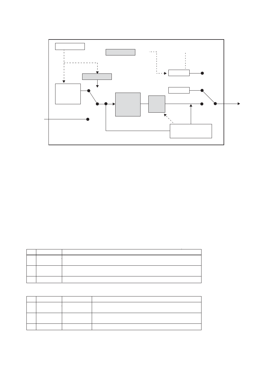
4.1.5 DI Block Parameters
F0405.EPS
Disable
Value
Operator
Operator
MAN
DI Block
Simulation
Value and
Status
Transducer
Block
Measured
Value
MODE and STATUS
Handling
AUTO
OUT_D
Target Mode
Simulation
FB
algorithm
Fail
Safe
Enable
Mode
handling
Out of
Service
OUT_D
OUT_D
Figure 4.5 Overview of DI Block
DI block parameters can be read or set from the host.
The AXF contains two DI blocks, which individually
transfer the “High Limit”, “Low Limit”, “Adhesion
Alarm” and “Adhesion warning” generated by the
transducer block. For a list of the parameters of blocks
held by the AXF, refer to Chapter 9.
TARGET_MODE:
Indicates the three types of function block modes;
Out_Of_Service (O/S), Manual, and Auto.
TARGET_MODE indicates what mode of operation is
desired for the block. In Out_Of_Service mode (O/S),
the DI block does not operate. The Manual mode does
not allow values to be updated. The Auto mode causes
the measured value to be updated. Under normal
circumstances, set the Auto mode to take effect. The
Auto mode is the factory default.
MODE_BLK:
The mode parameter is a structured parameter com-
posed of the actual mode, the normal mode and the
permitted mode.
Table 4.5
Data structure of MODE_BLK
1
Actual
The actual mode is set (calculated) by the block during its execution to reflect the
mode used during execution.
2
Permitted
The permitted mode shows which changes of the target mode is valid for the
specific block to the remote user of the MODE_BLK parameter.
3
Normal
The normal mode is the desired operating mode of the block.
Member
Description
T0406.EPS
Table 4.6
Initial value of MODE_BLK
1
Actual
2
Permitted
When the Actual of Physical Block is O/S, the Actual of DI
changes in O/S mode.
3
Normal
Auto
O/S, Man, Auto
Auto
Member
Initial value
Remark
T0407.EPS