Yokogawa AXFA14G/C User Manual
Page 42
IM 01E20F12-01E
5-18
5. EXPLANATION OF BASIC ITEMS
Alarm Message / Countermeasure Message
On the Integral LCD indicator, following messages are displayed when alarm is generated.
Table 5.6.5 Alarm Message Display
10:uP Fault
Microprocessor error
11:EEPROM Fault
EEPROM error
12:A/D(H) Fault
Contact nearest office or service center
13:A/D(L) Fault
A/D converter error
14:A/D(Z) Fault
15:Coil Open
Cut the power and check coil & EX cables Flowtube coil open-circuit
16:EEPROM Dflt
EEPROM default values
100:Comm uP Fault
Contact nearest office or service center
FB Microprocessor error
101:Comm EEPROM Fault
FB EEPROM error
102:Total1 Not Saved
Total1 had not been stored when the device was turned off.
103:Total2 Not Saved
Total2 had not been stored when the device was turned off.
104:Total3 Not Saved
Total3 had not been stored when the device was turned off.
105:Comm Error1
Contact nearest office or service center
Communication error
106:Comm Error2
Communication error
30 Sig Overflow
Check signal cable and grounding
Input signal error
31:Empty Pipe
Fill flow tube with fluid
Flowtube is not filled with fluid
33:Adhesion Alm
Clean electrodes
Electrode adhesion alarm
110:AI Lo Lo Alm
Check the flow rate and setting value.
Process alarm in AI function block.
111:AI Hi Hi Alm
Process alarm in AI function block.
40:PB O/S Mode
RS.TARGET_MODE is O/S mode.
41:TB O/S Mode
TB.TARGET_MODE is O/S mode.
42:AI FB O/S Mode
AI.TARGET_MODE is O/S mode.
43:Total1 FB O/S Mode
Total1.TARGET_MODE is O/S mode.
44:Total2 FB O/S Mode
Total2.TARGET_MODE is O/S mode.
45:Total3 FB O/S Mode
Total3.TARGET_MODE is O/S mode.
46:DI1 FB O/S Mode
DI1.TARGET_MODE is O/S mode.
47:DI2 FB O/S Mode
DI2.TARGET_MODE is O/S mode.
50:Span > 10m/s
Check parameter 27 of AI and 34 of TB
Span flow velocity setting is 11 m/s or more
51:Span < 0.1m/s
Span flow velocity setting is 0.05 m/s or less
57:Dens Set Err
Check parameter 34, 76 and 77 of TB
Mass units have been selected for Base Flow Unit but density is
set to 0.
71:Meas Mod Set
Check parameter 70 of TB
Measure_Mode is set to Enhanced DF without selecting an optional
specification code /HF1 or /HF2.
72:Size Set Err
Check parameter 31 and 32 of TB
A value of 3000.1 mm or more is set for Nominal_Size.
73:Adh Set Err
Check parameter 115 to 118 of TB
The condition in Adhesion detection level,
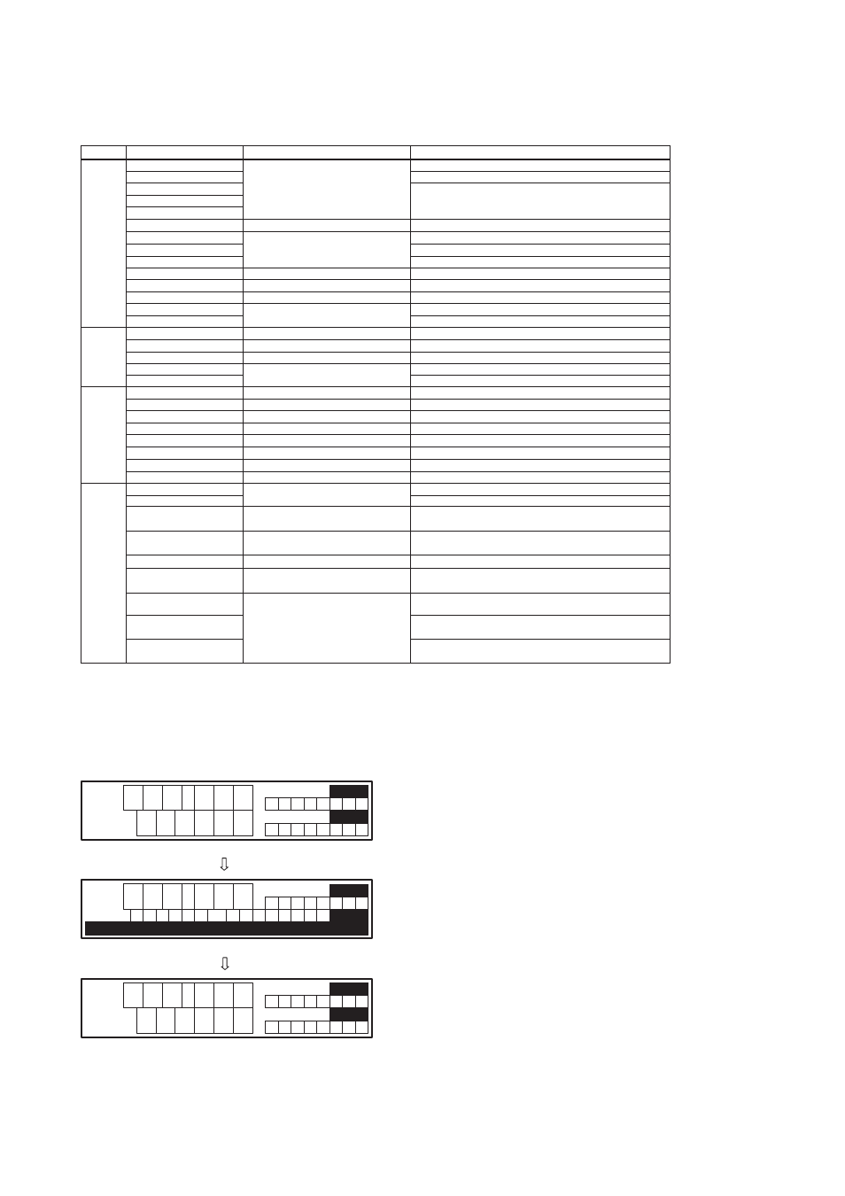
Level:1 120:Total1 Unit Set Err The mismatch of the unit set as TOTAL1 UNIT_TOT and VOLUME_FLOW_UNITS. 121:Total2 Unit Set Err Unify the unit between volume and mass. The mismatch of the unit set as TOTAL2 UNIT_TOT and VOLUME_FLOW_UNITS. 122:Total3 Unit Set Err The mismatch of the unit set as TOTAL3 UNIT_TOT and VOLUME_FLOW_UNITS. Category Category Display Display Message Message Countermeasure Message Countermeasure Message Alarm Description Alarm Description Process Alarms O/S Mode Alarms Setting System Alarms T0513.eps Warning Display When warning is generated, warning message is 9 9 9 . 9 9 l / h 1 2 3 4 5 6 9 M l F T L F R 9 9 9 . 9 9 l / h 9 2 3 4 5 6 M l 1 F T L F R p D 8 4 : i s n g r W e O v 9 9 9 . 9 9 l / h 1 2 3 4 5 6 9 M l F T L F R F0520.eps Normal mode screen Normal mode screen Alarm information screen
Alarms
displayed alternatively at the third line. Followings are
an example of warning display situation.