6 integral lcd indicator, 1 flow data display, Integral lcd indicator -12 – Yokogawa AXFA14G/C User Manual
Page 36: Flow data display -12
IM 01E20F12-01E
5-12
5. EXPLANATION OF BASIC ITEMS
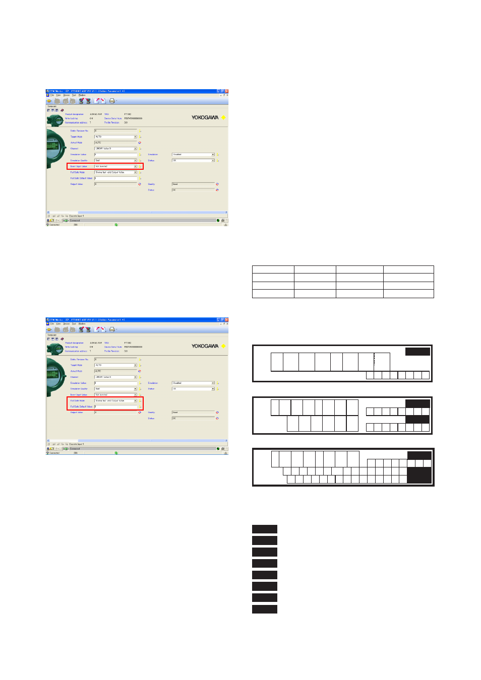
(3) Invert setting
Select a use of invert at [Invert Input Value] in each
[Discrete Input] menu.
Figure 5.5.19 Invert Input Value Setup
(4) Fail Safe Mode setting
Select the adequate mode and entry the value at [Fail
Safe Mode] along with [Fail Safe Default Value] in
each [Discrete Input] menu.
Figure 5.5.20 Fail Safe Mode Setup
5.6 Integral LCD Indicator
Employing 32*132 full dot matrix backlit LCD,
various display can be obtained.
5.6.1 Flow Data Display
By the transducer block parameters setting in DISPLAY_
SELECT1, 2, 3 as described in section 4.1.3, up to three
lines display can be made among the following data.
-Flow Rate(%)
-Out Value
-Flow Rate(Bar)
-Totalized Flow Rate1
-Totalized Flow Rate2
-Totalized Flow Rate3
-Tag No.
-Adhesion Check
-Communication
The number of the data can be configured by setting
DISPLAY_SELECT1, 2, 3 as follows;
1 line display
2 line display
3 line display
Display Select1
-
-
-
Display Select2
Off
Other than "Off"
Other than "Off"
Display Select3
-
Off
Other than "Off"
T0506.eps
Followings are the display examples depending on
choosing 1 to 3 value modes.
F0523.eps
1 2 3
.
4 5 6
8 7 6 5 4
M l
9
C O M
F R
F T L
P r o f i
b
P A
–
s
u
1 value mode
2 value mode
3 value mode
-
-
1 2 3 . 4 5 6
k g a l /
i n
m
F R
-
1 2 3
.
4 5
k g a
9 8 7 6 5 4
6
M l
F T L
F R
l /
i n
m
k g a l /
i n
m
The data titles are displayed together with the flow
data and units.
F0504.eps
F R
F T L
R T L
D T L
H T L
T A G
A D H
C O M
: Out Value Flow Rate
: Positive Total ( Forward Total )
: Negative Total ( Reverse Total )
: Balanced Total ( Differential Total )
: Hold Total
: Tag Number
: Adhesion Check
: Communication