3 transducer block parameters setup, Transducer block parameters setup -9 – Yokogawa AXFA14G/C User Manual
Page 33
IM 01E20F12-01E
5-9
5. EXPLANATION OF BASIC ITEMS
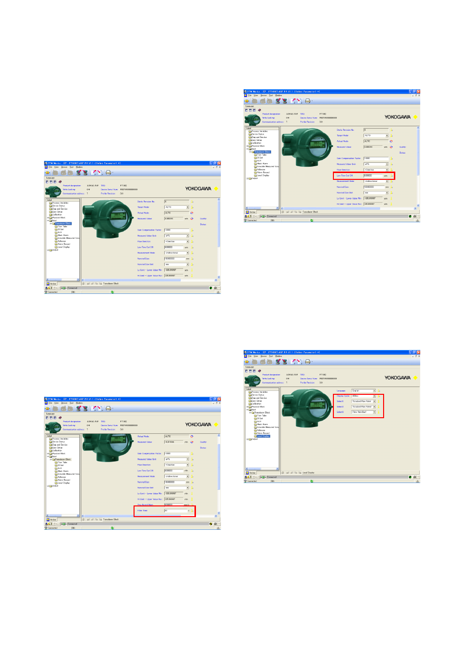
5.5.3 Transducer Block Parameters Setup
There are 8 kinds of submenus as [Flow Tube], [DI
Set], [AUX], [Mask Alarm], [Simulate Measured
Value], [Adhesion], [Alarm Record] and [Local
Display] in the [Transducer Block] menu.
Click [Input]
→ [Transducer Block] at the Navigation
tree.
Refer to section 6.3.4 for [Simulate Measured Value]
function.
Figure 5.5.7
Transducer Block menu
(1) Damping time constant setting
Entry the adequate numeric at [Filter Time] in the
[Transducer Block] menu.
This data is also available to set at [Filter Time] in the
[Easy Setup] menu.
Figure 5.5.8
Damping time constant Setup
(2) Output Signal Low Cut setting
Entry the adequate numeric at [Low Flow Cut Off] in
the [Transducer Block] menu.
Figure 5.5.9
Output Signal Low Cut Setup
(3) LCD Display setting
Select the adequate type of indication for the LCD
Display with its Display Cycle.
This data is also available to set at [Local Display] in
the [Easy Setup] menu.
Please note the AXF Profibus PA type is only available
to indicate English.
Figure 5.5.10 Local Display Setup