Operator's manual – Teledyne LeCroy CANbus TD and CANbus TDM - Operators Manual User Manual
Page 69
Operator's Manual
CANbus-TD-TDM-OM-E RevB
69
The Data Bytes are labeled D0 through D7. The far left bit in each byte is bit 7 and the far right
bit is bit 0. A “1” is always a dominant bit, and a “0” is always a recessive bit. An “X” means that
the bit can be either a 1 or a 0. Select a bit value by touching the existing value and choosing a
value from the pop-up menu. The data bytes shown in the Binary trigger setup dialog are
always in LSB (Least Significant Byte) format.
DLC value represents the number of total data bytes in the CAN message, not the number of
bytes you want to trigger on. If you want to trigger on bit values in the 3
rd
and 4
th
bytes in an 8-
byte CAN message, then you must select the DLC to be 8, and select “X” values in the portion of
the message that you don’t care to trigger on.
Using CAN as a Trigger Qualifier
Since the external CAN Trigger module is enabled with a simple pulse output and the standard
oscilloscope Edge trigger, it is possible to set up Qualified SMART Triggers using the CAN Trigger
pulse and another signal.
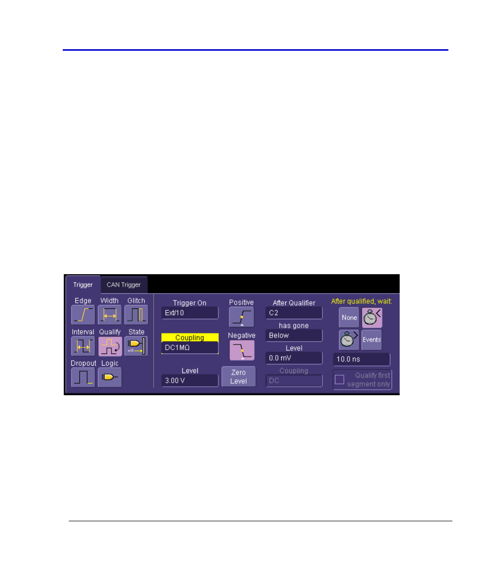
For example, let’s assume that you wanted to trigger on the CAN signal only after a different
signal (such as an analog signal) had gone above a certain threshold. You could use the LeCroy
Qualified SMART Trigger to set up that trigger condition, as shown below:
The “Trigger On” condition is that of the normal pulse output from the CAN Trigger module, and
the Qualifier is your analog signal.
You can also set up a Pattern (Logic) and State trigger similarly. This gives you powerful
additional capability beyond simple CAN or Edge triggering.