Canbus trigger, decode, and measure – Teledyne LeCroy CANbus TD and CANbus TDM - Operators Manual User Manual
Page 68
CANbus Trigger, Decode, and Measure
68
CANbus-TD-TDM-OM-E RevB
beginning of a data byte.
The # Bits can be any value from 1 to 24. If you enter a value
less than 1, it will default to 1. If you enter a value more than
24, it will default to 24. If you need to trigger on a data pattern
longer than 24-bits, you will need to use the binary trigger
setup (reference the separate section on how to set this up).
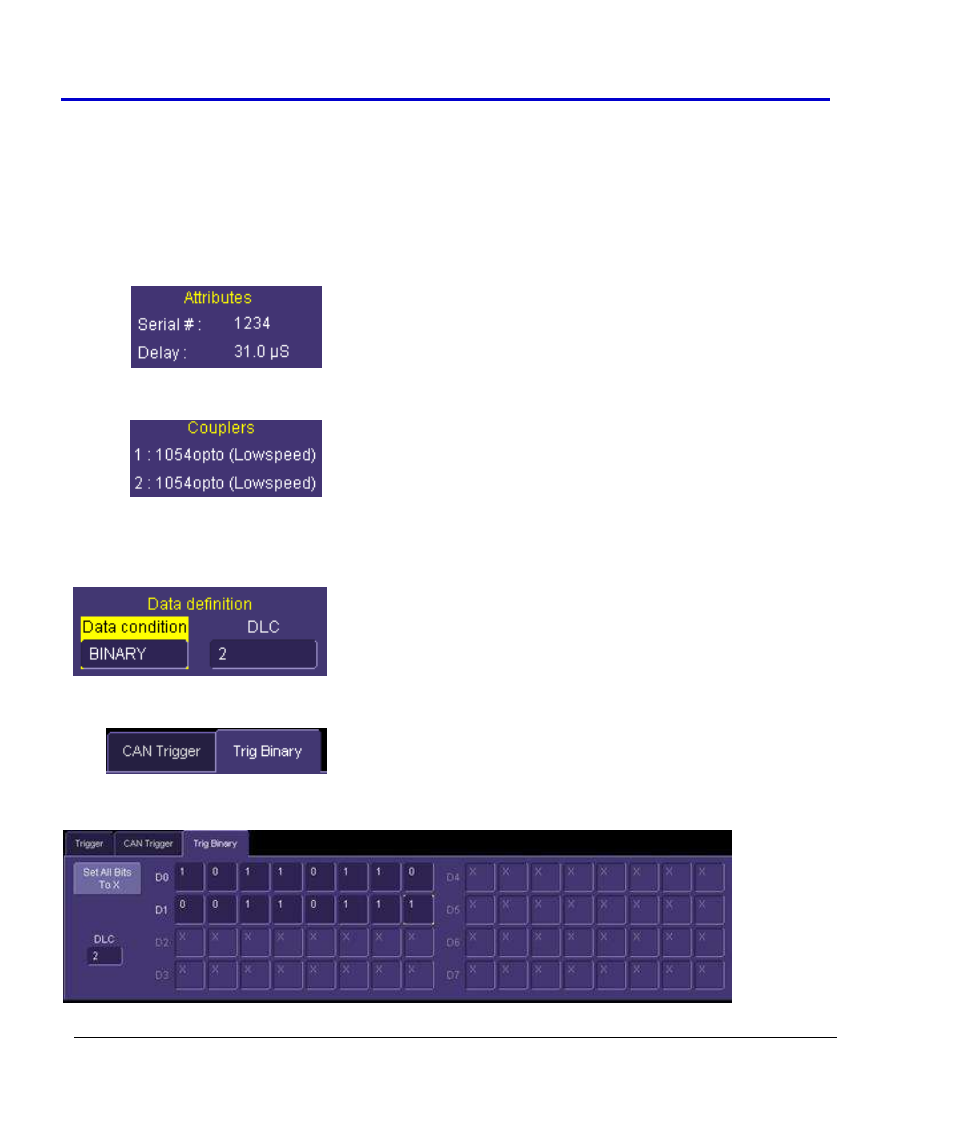
Attributes -- When the Trigger Module is correctly connected to
the oscilloscope, the serial number and delay setting are
displayed, for operator convenience. The delay setting is the
value of deskew applied to all oscilloscope channels (except for
the channel that the OIM may be connected to).
Trigger Couplers -- When the Trigger Module is correctly
connected to the oscilloscope, the Trigger Input (1 or 2) and the
Trigger Coupler type are identified. This makes it easy to
understand which Trigger Couplers are installed, and which
trigger input to use when connected to the bus.
Trigger Setup with Binary Data
Binary Data Condition – The CAN trigger can be set up in binary
format by selecting a “Binary” Data Condition in the Data
Definition section of the CAN Trigger dialog. You might want to
choose binary format setup when you want to trigger on less than
full nibbles of data, or when you want to trigger on more than 24-
bits of data.
When the Data Condition is set to “Binary”, an additional tab is
created in the Trigger Dialog. You will need to touch this tab
(shown at right) to get access to the Binary data setup dialog.
The Binary setup dialog is shown below: