Operator's manual – Teledyne LeCroy CANbus TD and CANbus TDM - Operators Manual User Manual
Page 53
Operator's Manual
CANbus-TD-TDM-OM-E RevB
53
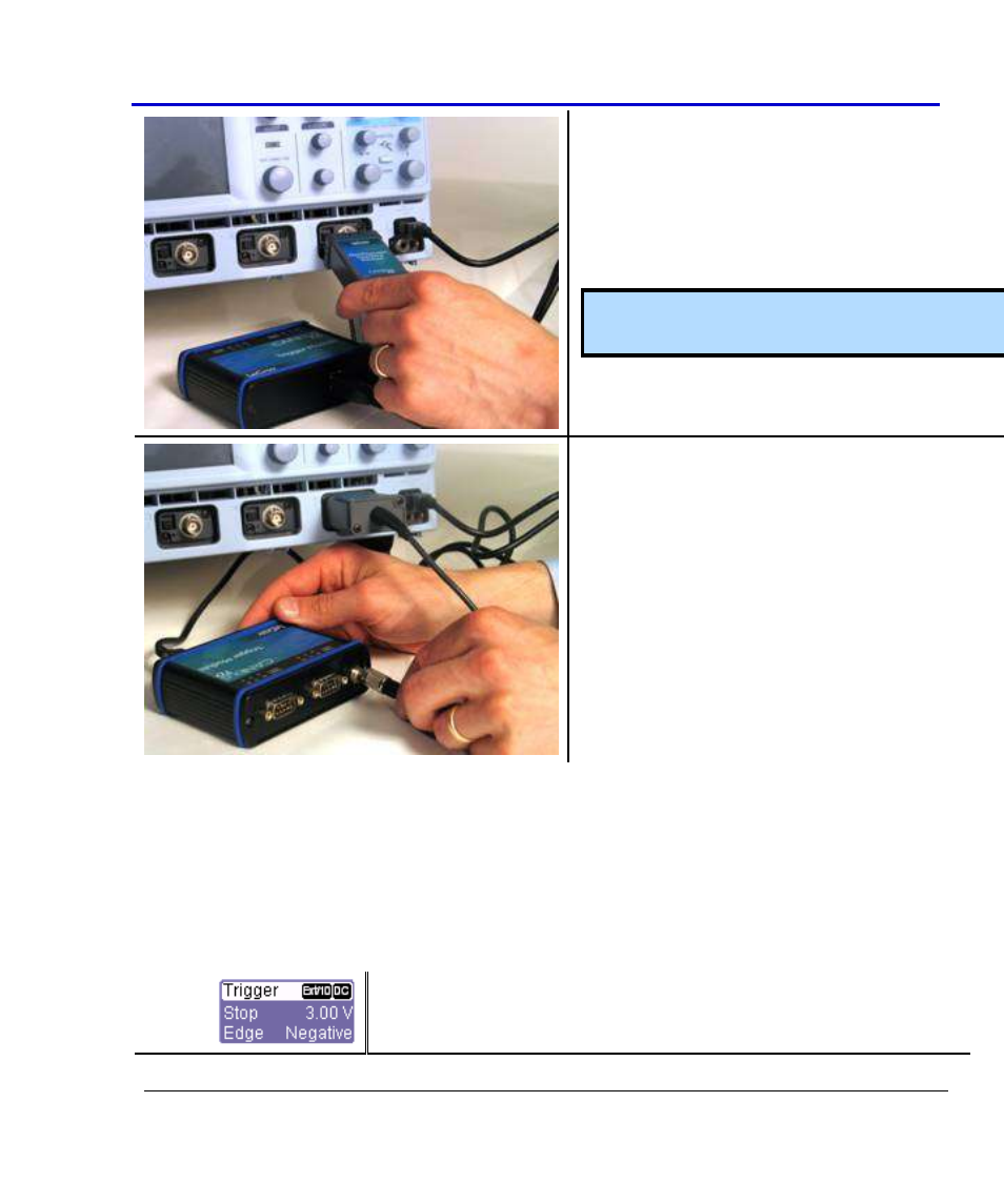
3. Connect the CANbus TD/TDM Oscilloscope
Interface Module (OIM) to the EXT input of
the instrument. Make sure that the top
(OIM labeled side) is facing up.
Note: Make sure that the OIM is at a right angle
to the connector.
4. Connect the 3-pin plug end of the OIM to
the Trigger Module.
Installing Trigger Couplers
U
NDERSTANDING
W
HICH
T
RIGGER
C
OUPLER IS
I
NSTALLED IN THE
T
RIGGER
M
ODULE
The Trigger Coupler is a CAN Transceiver. Therefore, the Trigger Coupler in the Trigger Module
must match the transceiver in the CAN circuit you wish to connect to. If it does not match, the
CAN trigger will not function properly.
To identify the coupler(s) that are installed, do the following:
1. Open the CAN Trigger dialog by touching the Trigger descriptor
box (or by pushing the front panel “Bus Analysis” push button
on Vehicle Bus Analyzers, and then selecting the CAN Trigger
- WaveAce EasyScope Operators Manual (28 pages)
- PeRT3 Software Interface (15 pages)
- FireInspector Automation Application Programming Interface (92 pages)
- PETracer ProtoSync Software User Manual (154 pages)
- QPHY-PCIe3-Tx-Rx (32 pages)
- Signal Integrity Studio (14 pages)
- Serial Data Debug Solutions (204 pages)
- Line Code and Symbolic Decoders (20 pages)
- AORM - Advanced Optical Recording Measurements (125 pages)
- CANbus TD - Quick Reference Guide (8 pages)
- FlexRay Trigger, Decode and Physical Layer Test (32 pages)
- MIPI D-PHY (15 pages)
- DFP2 - Digital Filter Package 2 (22 pages)
- ET-PMT - Electrical Telecom Pulse Mask Testing (11 pages)
- ENETbusD Decoder (16 pages)
- Eye Doctor II (45 pages)
- JitKit (16 pages)
- JTA2 (31 pages)
- Power Analyzer Package (34 pages)
- QPHY-10GBase-KR (28 pages)
- QPHY-10GBase-T (36 pages)
- QPHY-BroadR-Reach (33 pages)
- QPHY-DDR2 (47 pages)
- QPHY-DDR3 (44 pages)
- QPHY-DDR4 (73 pages)
- QPHY-DisplayPort (19 pages)
- QPHY-ENET (78 pages)
- QPHY-HDMI (37 pages)
- QPHY-LPDDR2 (49 pages)
- QPHY-MIPI-DPHY (32 pages)
- QPHY-MOST150 (24 pages)
- QPHY-MOST50 (21 pages)
- QPHY-PCIe (30 pages)
- QPHY-PCIE3 (28 pages)
- QPHY-SAS2 (45 pages)
- QPHY-SAS3 (50 pages)
- QPHY-SATA (45 pages)
- QPHY-USB (66 pages)
- QPHY-USB3-Tx-Rx (47 pages)
- QPHY-UWB (30 pages)
- SDA II (38 pages)
- SDA III-CompleteLinQ (59 pages)
- Spectrum Analyzer (14 pages)
- USB2 Decoder (24 pages)