Cantoanalog, Canbus trigger, decode, and measure – Teledyne LeCroy CANbus TD and CANbus TDM - Operators Manual User Manual
Page 22
CANbus Trigger, Decode, and Measure
22
CANbus-TD-TDM-OM-E RevB
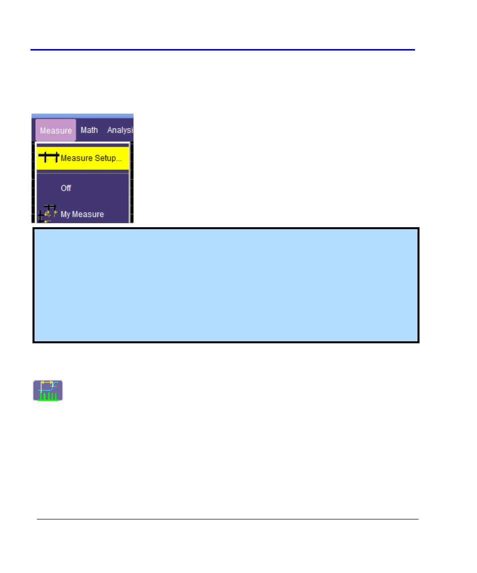
Setting Up CANbus Parameters using the Measure Setup option
You can also set up measurement parameters using the Measure menu as follows:
Touch Measure→Measure Setup. select the appropriate CAN or other parameter. For more
information, see Parameter Setup in the oscilloscope's Online Help or Operator's Manual.
Note: All CAN measurement parameters (with the exception of CAN Load %) calculate as many
values as possible during each acquisition. If there are 10 timing events that meet the set
condition during a specific acquisition, 10 timing event measurements will be returned.
However, the VALUE shown in the measurement table is the last measurement made. To view
statistical data (i.e., number of measurements made, mean, min, max, std. dev.), turn Statistics
ON.
CAN Load % returns only one value during each acquisition, since it is evaluating the load % for
the entire acquisition time.
CAN-to-Analog or Analog-to-CAN Measurement Parameter
CAN Message to Analog Signal timing (CANtoAnalog)
This measurement parameter is used to measure timing from either a CAN Message to an
Analog Signal, or from an Analog Signal to a CAN Message. The Frame Type, ID, DATA, etc.
conditions for the CAN message can be fully defined, as can the slope, level, etc. conditions for
the analog signal transition.
If measuring from CAN to Analog, the timing is always measured from the End of Frame of CAN
message to the analog signal transition. If measuring from Analog to CAN, the timing is always
measured from the analog signal transition to the Start of Frame of the CAN message.