Canbus trigger, decode, and measure – Teledyne LeCroy CANbus TD and CANbus TDM - Operators Manual User Manual
Page 54
CANbus Trigger, Decode, and Measure
54
CANbus-TD-TDM-OM-E RevB
dialog). With the Trigger Module connected to the instrument,
the Trigger Dialog will default to the CAN Trigger tab.
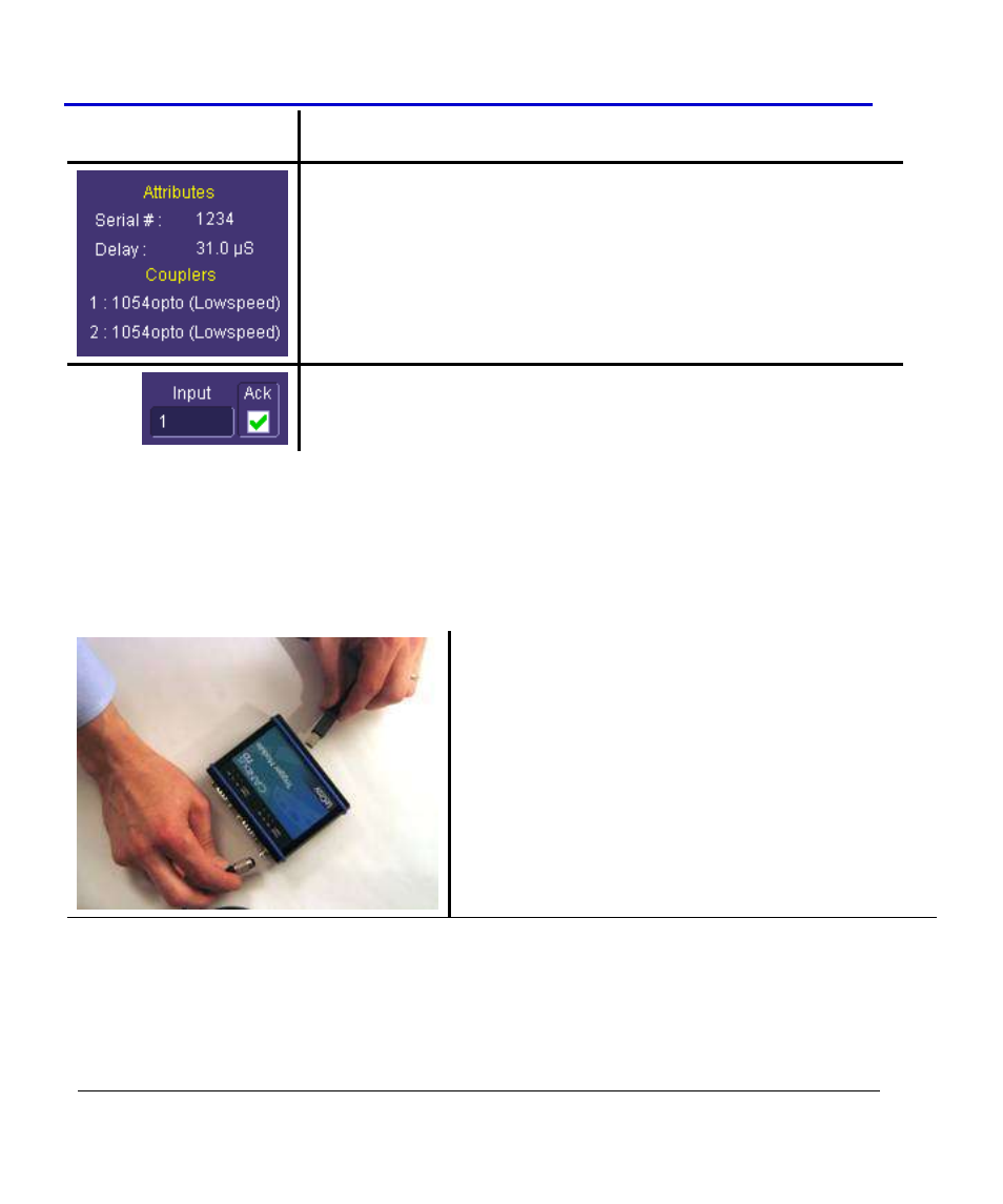
2. On the right hand side of the CAN Trigger dialog, there is a
listing of Trigger Couplers. Note the Input # and the Type. If
the correct Type of Trigger Coupler is installed, make sure you
connect that Trigger Module Input to your circuit using the
appropriate cable.
3. Trigger Module Input (and hence, Trigger Coupler) used for
triggering may be selected from the CAN Trigger dialog “Input”
selection.
I
NSTALLING OR
R
EMOVING A
T
RIGGER
C
OUPLER
You will probably only need to use one or two different Trigger Couplers, so this will probably be
something that you only have to do once, or very infrequently. In any case, it is simple to do.
The CANbus TD/TDM Trigger Module housing can be opened easily. Follow the instructions
below to open the Trigger Module and install or remove a Trigger Coupler.
1. Unplug the USB2.0 and OIM cable (if they are
plugged in).