Canbus decode setup detail, Canbus trigger, decode, and measure – Teledyne LeCroy CANbus TD and CANbus TDM - Operators Manual User Manual
Page 14
CANbus Trigger, Decode, and Measure
14
CANbus-TD-TDM-OM-E RevB
When using an in range or out of range Data Condition (previous), specify a Data Value
To value for triggering.
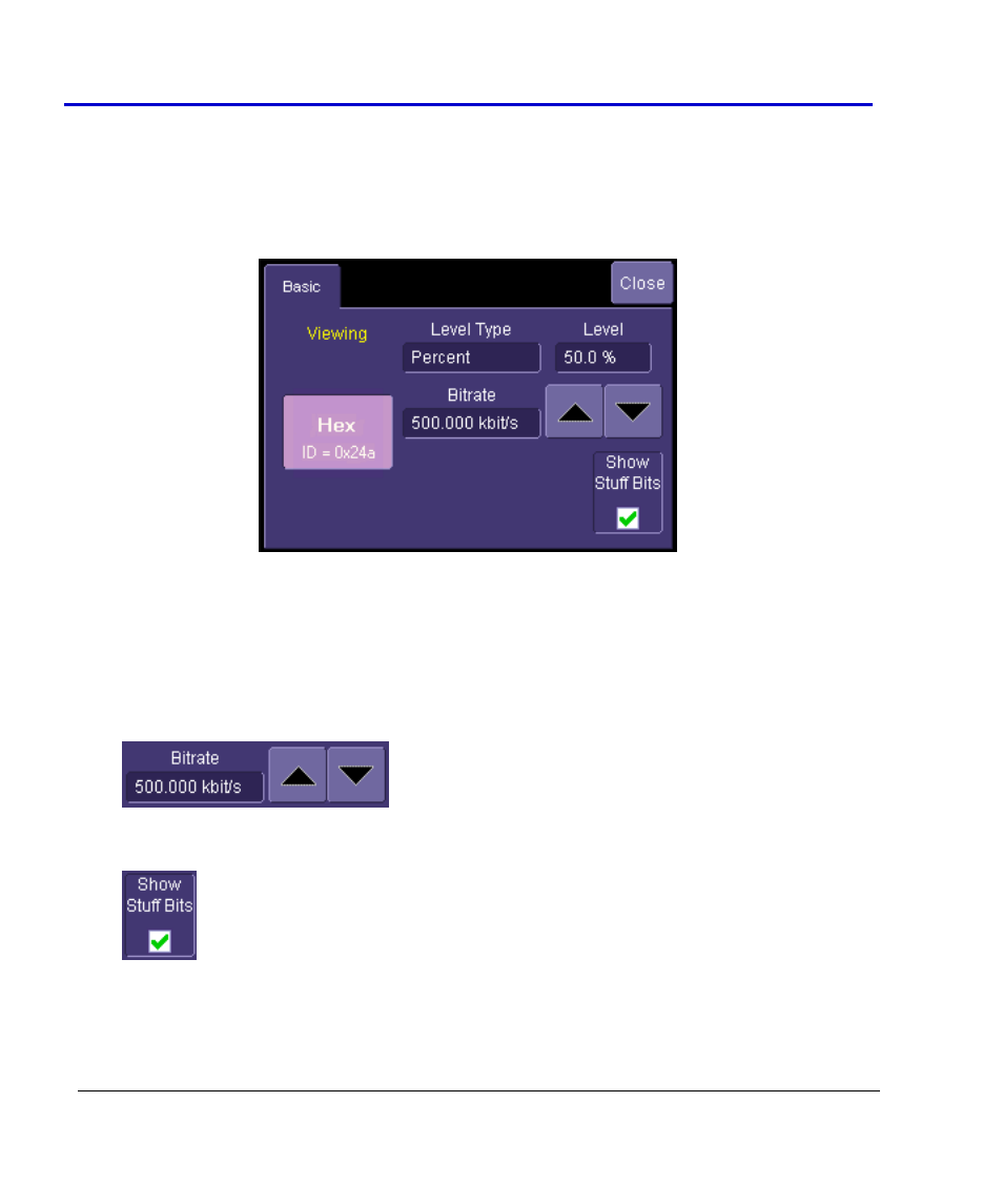
CANbus Decode Setup Detail
CANbus Decode Setup Right-Hand Dialogs are shown when CAN is selected as the decode
protocol. It provides detailed fields and setup conditions as follows:
Viewing - The decode format is displayed here as Hexadecimal for CANbus.
Bitrate - Adjust the bit rate value here to match the bit rate on the bus you are connected
to. This bit rate selection is dynamically linked to the decoding bit rate (they are always
the same value). Use the arrows to move through standard bit rates (10, 25, 33.333, 50,
83.333, 100, 125, 250, 500, and 1000 kb/s) and make a selection. Or, touch the number
twice (with a finger, or using a mouse) and open the pop-up keypad to enter the value
directly. Any value from 10-1000 kb/s may be entered in this way.
Show Stuff Bits – Use this checkbox to indicate whether you want stuff bits highlighted
on each CAN message frame.
Level Type and Level - The message decoding algorithm setup is performed here. The
level is normally set up in %, and defaults to 50%. To adjust the level, touch inside the
number area to highlight the box title in yellow, then use the oscilloscope front panel