Canbus trigger, decode, and measure – Teledyne LeCroy CANbus TD and CANbus TDM - Operators Manual User Manual
Page 26
CANbus Trigger, Decode, and Measure
26
CANbus-TD-TDM-OM-E RevB
CANtoCAN Measurement Parameter Setup Detail
To access the setup dialog, touch Setup for that particular parameter on the CAN
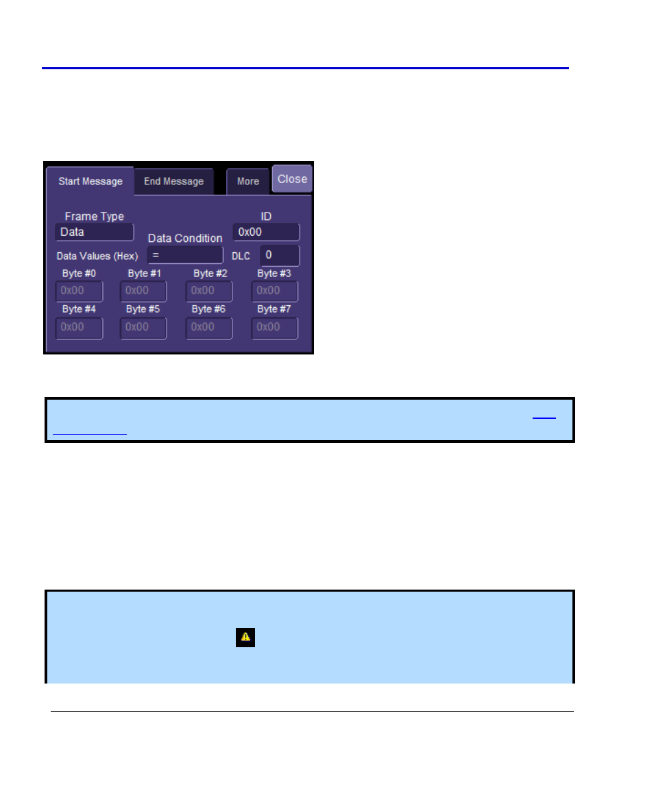
Measure/Graph Setup dialog. The Px Parameter dialog is displayed. On the right side of this
dialog box, there is a setup dialog labeled with the measurement parameter name. Touch the
tab with the parameter name on it to access the following dialog:
The Start Message tab defines the first CAN Message Setup. The End Message tab defines the
second CAN Message Setup.
Note: The CAN Message setup is nearly identical to the setup of the CAN message in the
, so details will not be repeated here.
The two CAN message definitions can be different, or they can be the same. If they are different,
the time value measured will be from the first CAN message to the second, with a positive value
indicating that the second message occurred after the first message, and a negative value
indicating that the second message occurred before the first.
If you wish to measure the time between two identical CAN messages, the Data Condition must
be set to “Don’t Care.” Then, if there are “n” CAN messages that satisfy the condition, you will
get “n-1” measurements. Measurements would be made between all adjacent pairs that satisfy
the condition.
Note: Various pathological conditions can block the computation of the CANtoAnalog and
CANtoCAN parameters. In all cases, the cause of the condition can be viewed on the message
line by clicking on the yellow icon
, below the measurement parameter values.
The simplest, and most common, reason for non-computation of the CAN timing parameters is