Operator's manual – Teledyne LeCroy CANbus TD and CANbus TDM - Operators Manual User Manual
Page 57
Operator's Manual
CANbus-TD-TDM-OM-E RevB
57
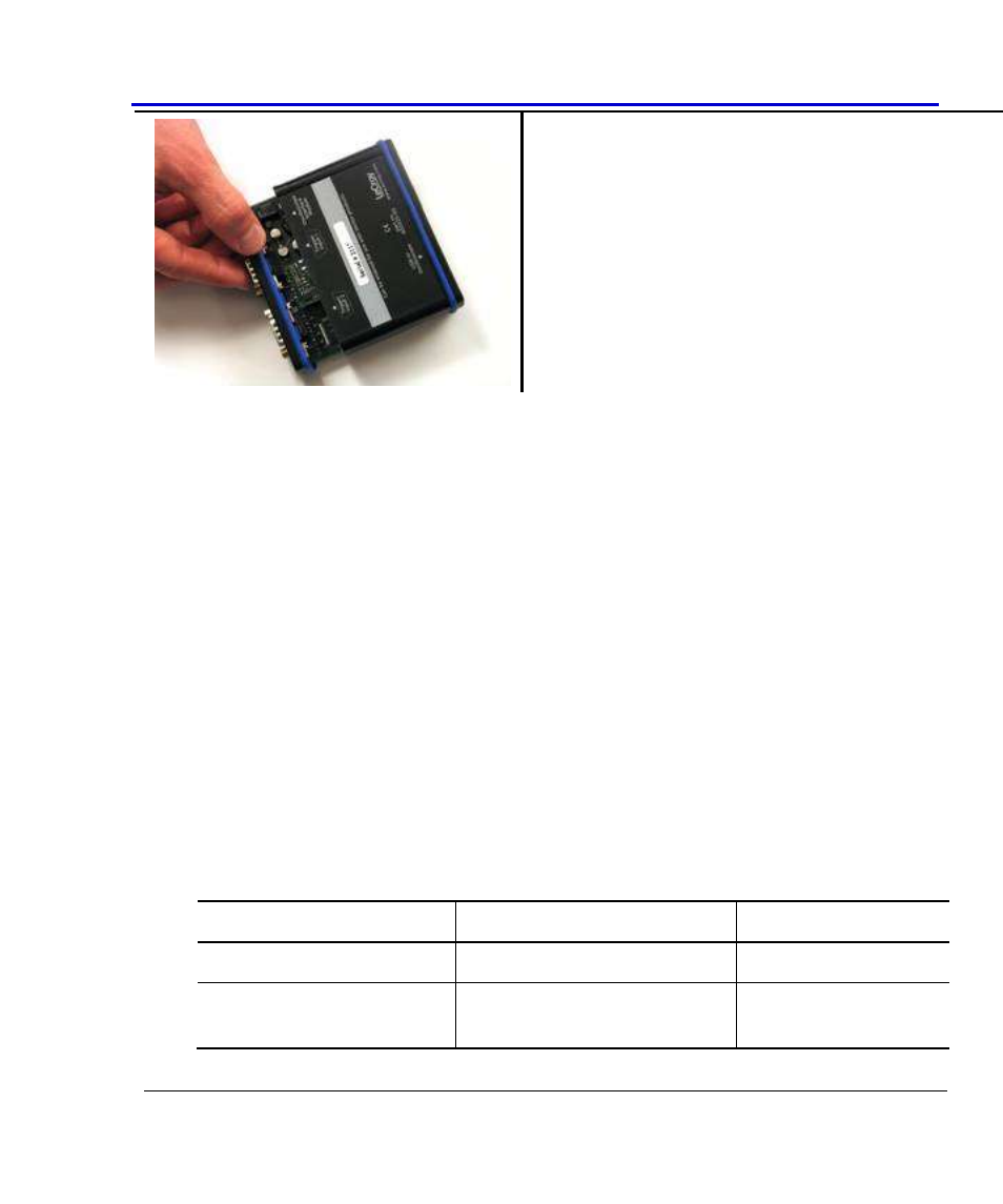
7. Slide the tray back into the housing, making
sure that when the tray is re-installed the USB
connector is showing.
8. Push the tray and the housing together, with
light pressure. Tighten the screws firmly but not
excessively.
Connecting the Trigger Module to the CAN Bus
Since the Trigger Module is a “node” on the CAN Bus, all of the normal connection rules apply.
The bus must be terminated correctly, and CANH, CANL, GND, etc. must be connected to the
correct locations. If you don’t make corrections to the bus correctly, the CANbus TD/TDM
Trigger Module may generate error frames, may load down your signal, and will not trigger.
Fortunately, LeCroy provides a number of standard cables to enable you to easily make
connections to high-speed, low-speed, and single-wire CAN Buses. These cables have 9-pin
DSUB socket connectors with 2 or 4 wires that are stripped and may be connected to in-circuit
wiring, banana plugs, alligator clips, etc., as necessary to connect to the CAN Bus circuit. The
part numbers for these cables are 902381-00 and 902382-00. They are usable for most
applications.
First, understand whether your CAN circuit is low-speed, high-speed, or single-wire. Then, plug
the correct cable’s 9-pin DSUB connector into the Trigger Module, and connect the wires to the
CANH, CANL, and other (as necessary).
Reference the tables below for information on the cables:
Cable Part Number 902382-00
DSUB (9-pin) Pin #
Definition
Wire Color
2
CANL
White
3
GND (low-speed) or VB- (single-
wire)
Brown