Operator's manual – Teledyne LeCroy CANbus TD and CANbus TDM - Operators Manual User Manual
Page 61
Operator's Manual
CANbus-TD-TDM-OM-E RevB
61
Viewing the CAN Bus Signal on the Instrument
The CANbus TD/TDM Trigger Module input is only providing a trigger signal to the instrument. It
doesn’t “pass through” an analog CAN signal to the scope for viewing. Therefore, you must use
a probe to connect to the CANH and CANL lines on the CAN Bus.
A differential probe is ideal since CAN is a differential signal. And a differential probe, such as
the LeCroy AP033 or ADP305, does not require you to connect to system ground, and may
provide better signal fidelity. It also uses only one channel on the instrument, which is a benefit
if you want to view the CAN signal and many other analog signals on the instrument.
If you do not have a differential probe, two single-ended probes may be used instead. Be sure
that the probes are grounded properly, and that the CAN Trace is properly configured for single-
ended probe usage. Also, for best results, make sure that the gain and offset settings for the
two probes are identical.
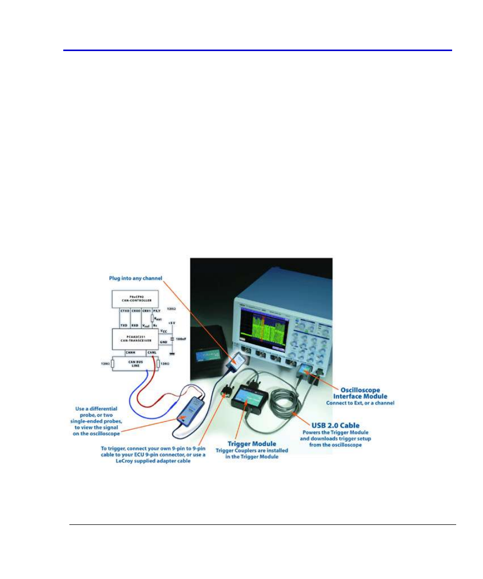
The Complete System Connection
When your system is completely connected, it will look like the photo and drawing that follows: