Appendix a: external trigger hardware, Canbus td standard hardware, Canbus trigger, decode, and measure – Teledyne LeCroy CANbus TD and CANbus TDM - Operators Manual User Manual
Page 48
CANbus Trigger, Decode, and Measure
48
CANbus-TD-TDM-OM-E RevB
Appendix A: External Trigger Hardware
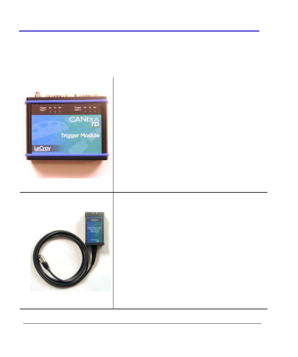
CANbus TD Standard Hardware
The Standard Hardware consists of the following items:
Qty. 1: Trigger Module -- The Trigger Module is basically a
CAN Node that is set to filter (and provide a triggering
signal) when certain conditions are met. It contains a 32-
bit, 64 MHz microcontroller and two Philips SJA1000 CAN
controllers. A Trigger Coupler (CAN transceiver) needs to
be installed in the trigger module to connect to the
appropriate bus. A 251 Trigger Coupler is provided
standard on input 1, and a second can be installed on input
2. As necessary, the trigger couplers can be interchanged
to suit your specific needs. The Trigger Module receives
triggering instructions, as defined in the CAN Trigger dialog,
through the USB2.0 cable (connected to the LeCroy
oscilloscope), and outputs a trigger pulse through the 3-pin
connector when the CAN trigger condition is met. The
trigger pulse is a negative going edge from 5 V to 0 V.
Qty. 1: Oscilloscope Interface Module -- This module
connects to the Trigger Module via the 3-pin connector.
The module is LeCroy ProBus
®
compatible. When plugged
into a LeCroy oscilloscope, it is automatically recognized
and proceeds with appropriate setup for CAN triggering.
The OIM can be connected to any channel, but is more
commonly connected to the EXT input (to reserve a channel
for an analog signal). Once connected, it sets the following:
sets the oscilloscope trigger to a negative going Edge
with a trigger level of 3 V (to trigger on the output
pulse when the CAN trigger condition is met) and no
trigger holdoff condition.
displays the CAN trigger dialog
applies a skew correction to all channels (to ensure
that the trigger point aligns with the EOF point of the