Canbus tdm parameters, Canbus trigger, decode, and measure – Teledyne LeCroy CANbus TD and CANbus TDM - Operators Manual User Manual
Page 16
CANbus Trigger, Decode, and Measure
16
CANbus-TD-TDM-OM-E RevB
Some of this information could be gathered using standard oscilloscope tools, but the
accumulation of the data would take hours or days. It is more likely that the engineer would
instead gather a very small sample set and skip the statistical evaluation in order to save time.
The result is reduced product quality and corresponding greater risk of shipping product that
functions incorrectly in some situations.
CANbus TDM contains specific CAN measurement parameters that allow you to quickly and
easily accumulate statistical information on a wide variety of events, and graphical display tools
to visualize the data on your oscilloscope screen. These sophisticated measurement and
graphical display tools are the “missing link” between standard oscilloscope and protocol
analyzer capability. The CANbus TDM tools provide the capability to trigger on defined CAN Bus
events, observe actions/reactions, measure timing among CAN and Analog signals, and view
results in a graphical fashion directly on the oscilloscope display with no complicated export of
data. Data on tens of thousands of events can be automatically and quickly gathered and
analyzed in a fraction of the time it takes to manually perform the same testing.
CANbus TDM contains additional CAN specific measurement, graphing, and statistical analysis
capability as the following topics explain.
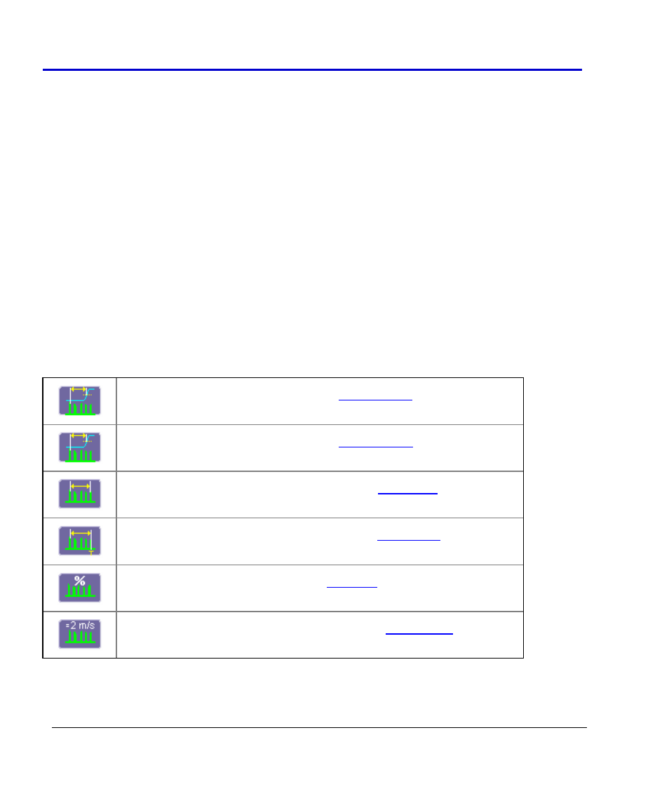
CANBUS TDM Parameters
CAN Message to Analog Signal timing (
Analog Signal to CAN Message timing (
CAN Message to CAN Message Signal Timing (
Time from trigger to a specific CAN message (
CAN Bus Message Load Percentage (
Extract CAN Message Data to a Decimal Value (