Detailed installation, 1 system components/packing list, 2 the installed ibtracer 4x unit – Teledyne LeCroy IBTracer 4X - Users Manual Ver.2.30 User Manual
Page 21: Led and button descriptions, Chapter 3 detailed installation, 2 the installed ib tracer 4x unit
13
IBTracer 4X Protocol Analyzer User’s Manual
CATC
SW Version 2.3
3. Detailed Installation
3.1 System Components/Packing List
•
One stand-alone IBTracer 4X Analyzer module
•
One Universal Protocol Analyzer System 10000 Chassis
•
One USB cable
•
One 6-foot (2-meter) 4x to 4x cable
•
Two 6-foot (2-meter) Infiniband 4x to 1x cables
•
One DB-25 parallel cable
•
One UPAS External Breakout Board
•
IBTracer 4X software program installation CD-ROM
•
Product documentation
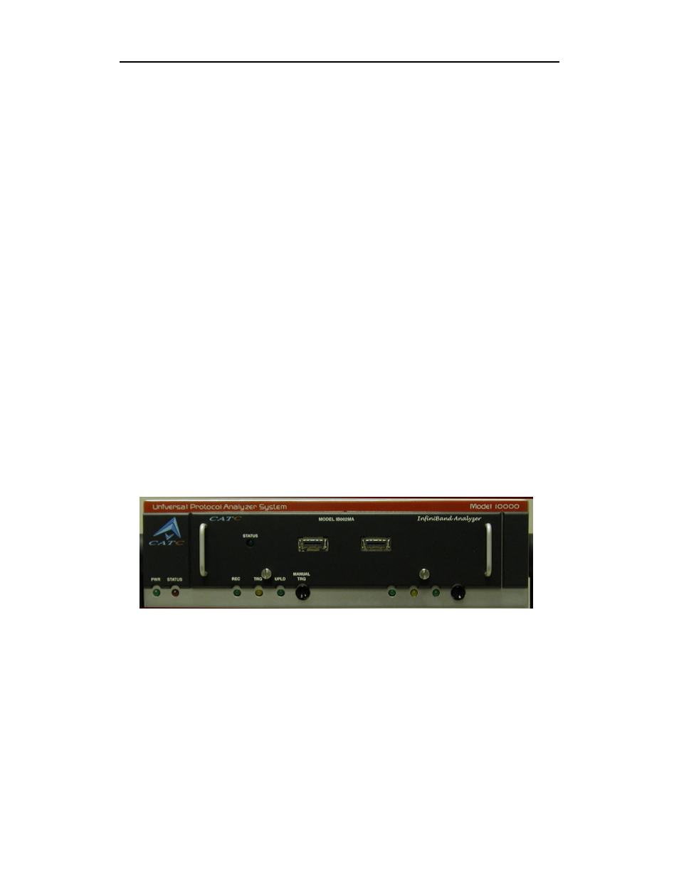
3.2 The Installed IBTracer 4X Unit
If you purchased an IBTracer 4X module with a UPAS, the IBTracer 4X
module will arrive inserted into the UPAS. Upon power up, the installed
IBTracer 4X Analyzer will activate the user-accessible controls and LEDs
on the front and rear panels of the UPAS.
Figure 1: Front Panel
LED and Button Descriptions
If you look at the front panel, you will see LEDs, buttons, and connectors.
Left-most LEDs
•
Green PWR (power) indicator LED for UPAS (lights when the unit
power is switched on).
•
Red Status indicator LED for UPAS (lights during the boot up).