Mode flow chart – IAI America IA-T-XD User Manual
Page 12
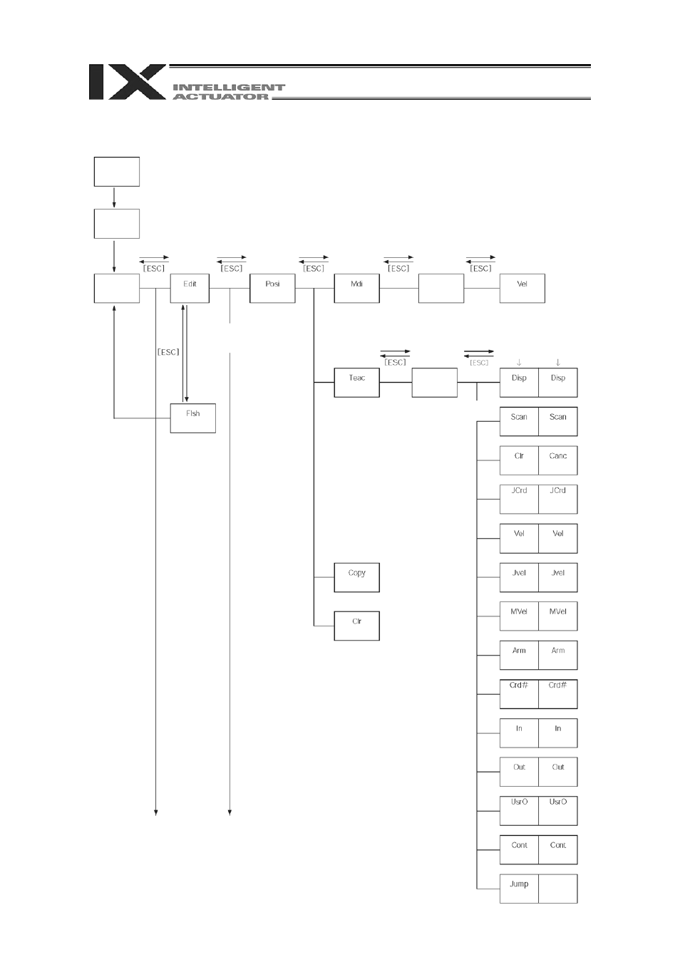
7. Mode Flow Chart
(Continuous
movement)
(Jog velocity)
(User-specified
output port
monitor)
(Output
monitor)
(Velocity data)
(Coordinate
system No.
change)
(Arm system
change)
(Input
monitor)
(Movement
velocity)
(Jog
coordinate
system)
(Cancel)
(Data import)
(Display
change)
(Jump
movement)
(Continuous
movement)
(Jog velocity)
(User-specified
output port
monitor)
(Output
monitor)
(Velocity data)
(Coordinate
system No.
change)
(Arm system
change)
(Input
monitor)
(Movement
velocity)
(Jog
coordinate
system)
(Clear)
(Data import)
(Display
change)
Cursor
position data
Cursor
position No.
(Velocity input)
Function key
(Copy/movement)
(Clear)
* After writing data with [WRT],
move to the next position
Position data
input
(Teach)
Select position No.
and press return
Function key
(Write to
Flash ROM)
“Yes” or “No”
* When escaping the mode
with [ESC], check whether to
write to Flash ROM.
* After writing data with [WRT],
move to the next position
Position data
input
(Position) (M
t)
anual
inpu
Select position No.
and press return
Function key
Function key
Function key
(Edit)
Mode
selection
Communications
established
Power ON
9