IAI America RCS-C User Manual
Page 60
50
Each output
Pin No.
Rectifier
Internal circuit
Fuse resistance:
Load
Load
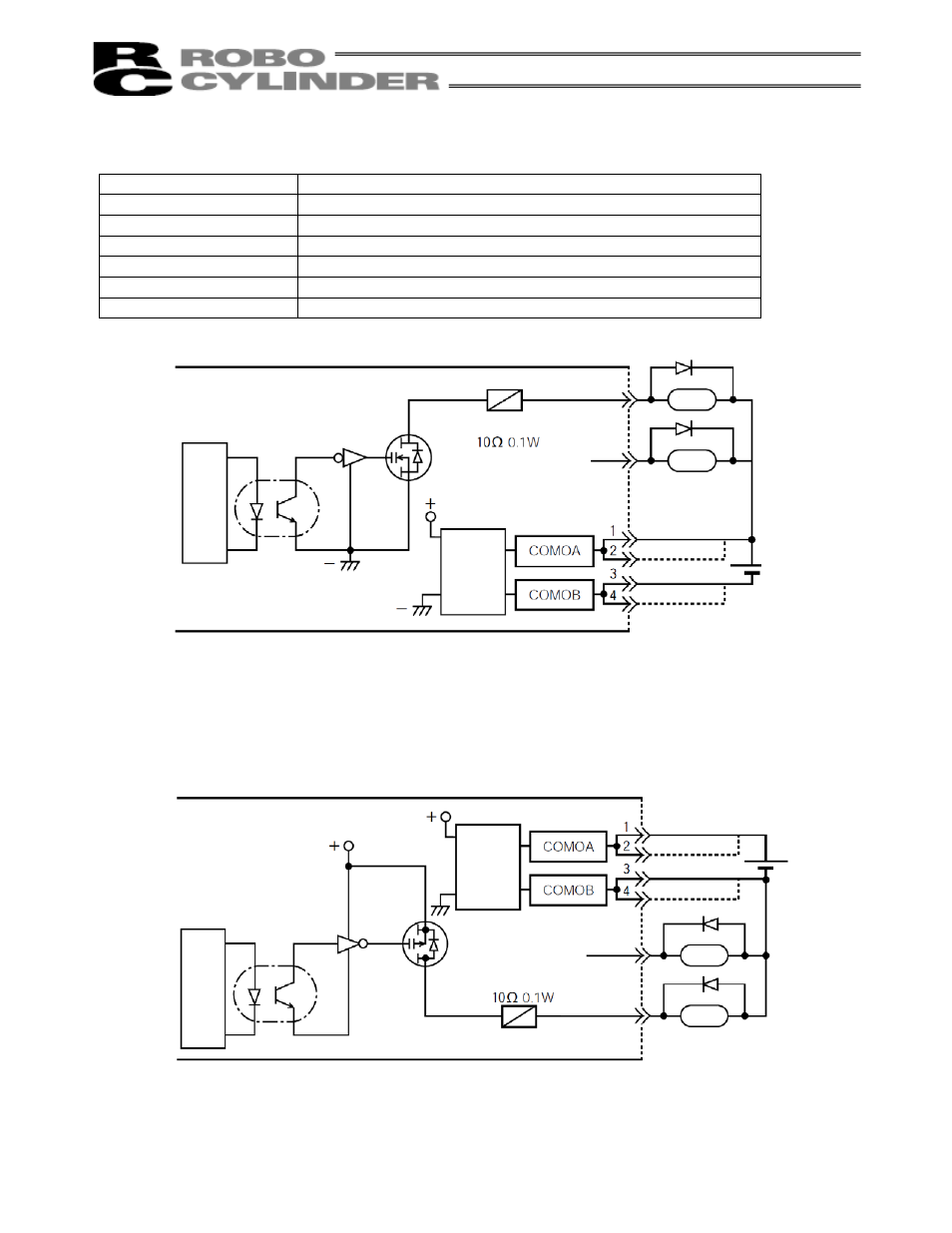
Output Part
100-mA output circuit by power MOSFET
Item Specification
Number of output points 11 points
Rated load voltage
24 VDC; 60 VDC (peak) (without flywheel diode)
Maximum load current
100 mA per point
Residual voltage
1.8 V / 100 mA
Isolation method
Photocoupler
Overcurrent protection
Fuse resistance: 10
0.1 W
Internal circuit configuration (Standard NPN specification)
Supply 24 VDC between COMOA and COMOB.
Pin Nos. 1 & 2, and 3 & 4, are connected internally.
Note 1) The output circuit is an open-drain circuit provided by a power MOSFET and has no flywheel diode.
When connecting a load, such as a relay, also connect a diode, etc., to suppress flyback voltage.
(Spike noise can be eliminated most effectively when a diode is connected at the closet possible
position to the coil).
Internal circuit configuration (Optional PNP specification)
External
power supply
24 VDC
Pin No.
Rectifier
Each output
Internal circuit
Fuse resistance:
Load
Load