2 external connection diagram, External connection diagram – IAI America RCS-C User Manual
Page 55
45
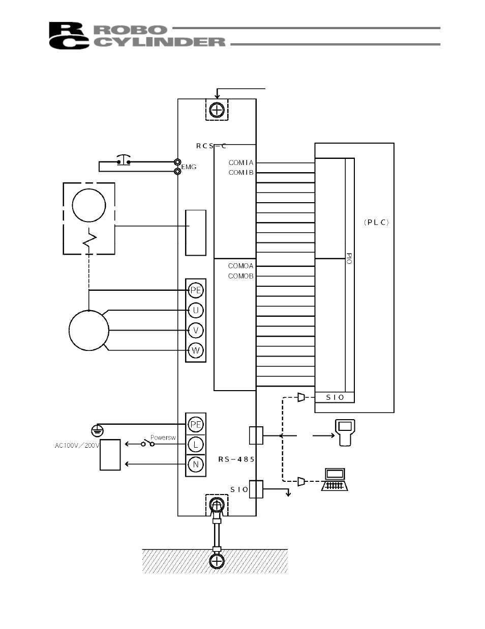
3.6.2 External
Connection
Diagram
PC
To the next controller
Teaching pendant
Conversion adap
ter
Host
system
Output
Input
Start
Command position 1
Command position 2
Command position 4
Command position 8
Pause
Reset
Servo ON
Completed position 1
Completed position 2
Completed position 4
Completed position 8
Position complete
Home return
completion
Zone
Alarm
Moving
Emergency stop
Battery alarm
Screw onto a metal frame directly.
Controller
Metal frame
If the controller cannot be screwed onto the frame
directly, connect it to the frame over a minimum
distance using a cable of 0.75 mm
2
or larger.
Main
communication
port
Encoder
Power
supply
Motor
Encoder
Brake
See also other documents in the category IAI America Hardware:
- ERC2 (138 pages)
- ERC2 (188 pages)
- ERC3 (438 pages)
- ERC (153 pages)
- RCA-E (53 pages)
- RCA-P (42 pages)
- RCB-101-MW (38 pages)
- RCP2-C (178 pages)
- RCS-E (102 pages)
- RCA-A4R (72 pages)
- RCA-RA3C (114 pages)
- RCA-SRA4R (56 pages)
- RCA2-RA2AC (100 pages)
- RCA2-SA2AC (92 pages)
- RCA2-TA4C (134 pages)
- RCD-RA1D (40 pages)
- RCP2-BA6 (72 pages)
- RCP2-GRSS (130 pages)
- RCP2-HS8C (126 pages)
- RCP2-RA2C (120 pages)
- RCP2-RTBS (80 pages)
- RCP2W-SA16C (46 pages)
- RCP3-RA2AC (60 pages)
- RCP4-RA5C (82 pages)
- RCP4-SA5C (94 pages)
- RCP4W (96 pages)
- RCS2-F5D (142 pages)
- RCS2-GR8 (46 pages)
- RCS2-RN5N (80 pages)
- RCS2-RT6 (60 pages)
- RCS2-SA4C (258 pages)
- RCS2-TCA5N (62 pages)
- RCL-SA1L (66 pages)
- RCL-RA1L (56 pages)
- RCLE-GR5L (46 pages)
- IK Series (16 pages)
- FS (84 pages)
- IF (76 pages)
- ISB (114 pages)
- ISDA (126 pages)
- ISDB (116 pages)
- ISPWA (90 pages)
- NS (78 pages)
- ICS(P)A (16 pages)
- RS (46 pages)