3 pio interface, Pio interface – IAI America RCS-C User Manual
Page 34
24
2.6.3 PIO
Interface
A PIO interface list is given below.
The PIO cable is a flat cable with no connector attached on the end connected to the external equipment.
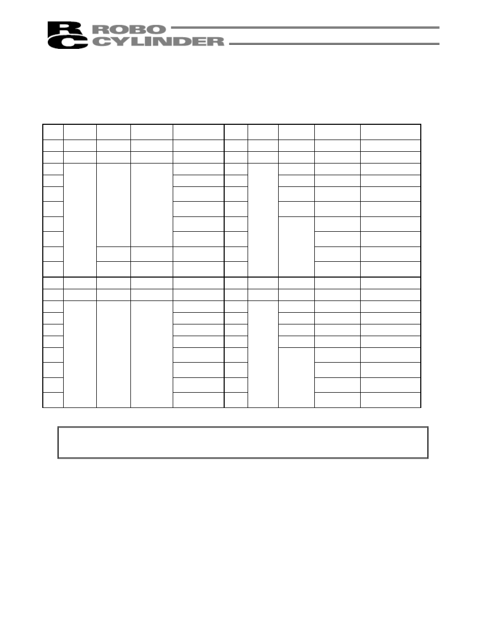
PIO connector (40 pins)
Pin
No.
Category
Reference
No.
Signal name
Cable color
Pin
No.
Category
Reference
No.
Signal name
Cable color
1 [1] COMOA Brown-1 2 [1] COMOA
Red-1
3 [2] COMOB
Orange-1 4 [2] COMOB Yellow-1
5 Green-1
6
[3]
*Alarm
Blue-1
7 Purple-1
8
[4]
Zone
Gray-1
9 White-1
10
[5]
Home return
completion
Black-1
11 Brown-2
12
[6]
Position
complete
Red-2
13 Orange-2
14
Completed
position 8
Yellow-2
15
NC
Green-2 16
Completed
position 4
Blue-2
17 [8]
Moving
Purple-2
18
Completed
position 2
Gray-2
19
Output
[9]
*Emergency
stop
White-2 20
Output
[7]
Completed
position 1
Black-2
21 [10] COMIA Brown-3 22 [10] COMIA
Red-3
23 [11] COMIB Orange-3 24 [11] COMIB
Yellow-3
25 Green-3
26
[12]
*Pause
Blue-3
27 Purple-3
28
[13]
Servo
ON
Gray-3
29 White-3
30
[14]
Reset
Black-3
31 Brown-4
32
[15]
Start
Red-4
33 Orange-4
34
Command
position 8
Yellow-4
35 Green-4
36
Command
position 4
Blue-4
37 Purple-4
38
Command
position 2
Gray-4
39
Input NC
White-4 40
Input
[16]
Command
position 1
Black-4
Note: The ports indicated by an asterisk (*) conform to the contact-b signal logic (always ON).
Never connect those ports that are not used.