IAI America RCS-C User Manual
Page 25
15
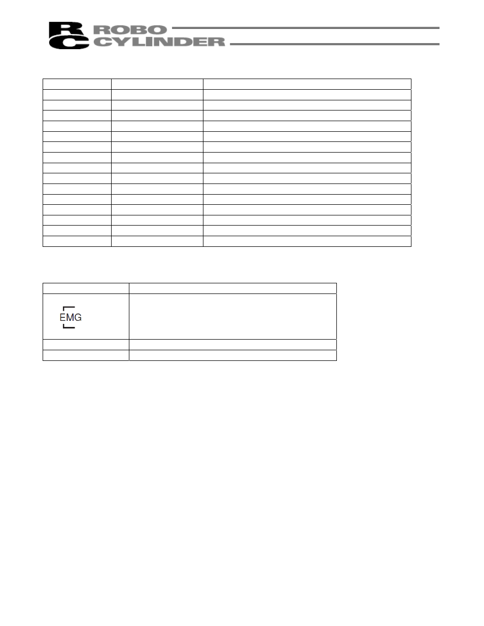
Encoder/brake connector [High-density D-sub, DE-15 type]
Pin No.
Signal name
Connected wire
1
EN A+
Encoder A+
2
EN A–
Encoder A-
3
EN B+
Encoder B+
4
EN B–
Encoder B-
5
EN Z+
Encoder Z+
6
EN Z–
Encoder Z-
7 SD+
Encoder
SD+
8 SD–
Encoder
SD-
9 BAT+
(Battery+)
10 GND
(Battery-)
11
EN 5
Encoder 5V+
12 EN
GND
Encoder
COM-
13 BK
N
Brake-
14 BK
P
Brake+
15 FG
Shield
Power/emergency-stop terminal block [Sato ML-800S IH (4P)]
Signal Name
Connected wire
[2]
[1]
These terminals are connected to the emergency stop
circuit.
24 V is output to [1].
(These terminals have been shorted prior to shipment.)
24 V
Positive side of the 24-V power supply
N
Negative side of the 24-V power supply
24 V and ENG [1] are connected internally.
See also other documents in the category IAI America Hardware:
- ERC2 (138 pages)
- ERC2 (188 pages)
- ERC3 (438 pages)
- ERC (153 pages)
- RCA-E (53 pages)
- RCA-P (42 pages)
- RCB-101-MW (38 pages)
- RCP2-C (178 pages)
- RCS-E (102 pages)
- RCA-A4R (72 pages)
- RCA-RA3C (114 pages)
- RCA-SRA4R (56 pages)
- RCA2-RA2AC (100 pages)
- RCA2-SA2AC (92 pages)
- RCA2-TA4C (134 pages)
- RCD-RA1D (40 pages)
- RCP2-BA6 (72 pages)
- RCP2-GRSS (130 pages)
- RCP2-HS8C (126 pages)
- RCP2-RA2C (120 pages)
- RCP2-RTBS (80 pages)
- RCP2W-SA16C (46 pages)
- RCP3-RA2AC (60 pages)
- RCP4-RA5C (82 pages)
- RCP4-SA5C (94 pages)
- RCP4W (96 pages)
- RCS2-F5D (142 pages)
- RCS2-GR8 (46 pages)
- RCS2-RN5N (80 pages)
- RCS2-RT6 (60 pages)
- RCS2-SA4C (258 pages)
- RCS2-TCA5N (62 pages)
- RCL-SA1L (66 pages)
- RCL-RA1L (56 pages)
- RCLE-GR5L (46 pages)
- IK Series (16 pages)
- FS (84 pages)
- IF (76 pages)
- ISB (114 pages)
- ISDA (126 pages)
- ISDB (116 pages)
- ISPWA (90 pages)
- NS (78 pages)
- ICS(P)A (16 pages)
- RS (46 pages)