Device diagnostics – E-Mon E-PS-S-HV-RTU User Manual
Page 17
Chapter 2 Operating the
PowerSmart Socket PQM
Device Diagnostics
PowerSmart Socket Power Quality Meter
17
kWh resolution. See
Energy Pulse LED Indicators
above for
the test LED pulse rates.
You can enter TEST mode directly by an extended press on
the TEST button located under the meter cover, or via Power
Software. See
The TEST Button
in Chapter 3 and
Device
Options and Mode Control
in Chapter 5 on how to put your
meter in TEST mode and to change the test LED pulse rate.
See
TEST Mode Data Display
for more information on the
TEST mode display.
NOTE
In TEST mode the following features are not operational:
•
setpoints
•
power quality recorder
•
fault recorder
•
relay outputs
•
instrument transformer correction
•
transformer/line loss compensation
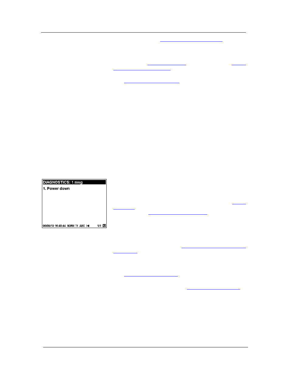
Device Diagnostics
Device diagnostic messages may appear as a result of the
PowerSmart Socket PQM built-in diagnostic tests performed
during start-up and device operation.
A blinking diagnostics indicator is shown on the display
whenever there are diagnostic messages. See
Status
Indicators
in Chapter 3 for information on diagnostics
indicators. See
Device Diagnostics Display
in Chapter 3 on
how to inspect the meter diagnostics messages from the
display.
The device diagnostics status is stored in a non-volatile
register, which may be inspected and cleared from the meter
display, via the supplemental Power Software software, or
from a user application. See
Viewing and Clearing Device
Diagnostics
in Chapter 6 on how to clear the device
diagnostics status in your meter.
All diagnostic events with time stamps are also recorded in
the meter Event log and can be inspected via Power Software
(see
Retrieving Recorded Files
in Chapter 7).
In the event of a device fault, check the fault reason and
clear the device diagnostics. See
Device Diagnostic Codes
in
Appendix H for the list of diagnostic messages and their
meanings. In the event of a time fault, update the device
clock. In the event of a configuration reset, check the setup
affected by the fault via the device Event log, and then verify
the setup data.
Hardware failures are normally non-critical recoverable faults
that do not cause a system failure but may cause data loss.
Hardware failures are often caused by excessive electrical