Discrete i/o, Outputs, Oring and not anding – Electro Cam PS-6144 Series User Manual
Page 88: Special purpose
6-16 Communications
Special Purpose
00301 - 00400 Special Purpose
301
Global Unforce
Clears all OR and NOT AND coils when set from '0' to '1' (edge active).
302
Pulse Register Enable
When '1', this coil enables the creation of new pulses through writes to the New Off
Register. When this coil is '0', writes to New Off Register do not create a new pulse.
303
Create New Pulse
Creates a new pulse defined by the New On and New Off registers when set from '0' to '1'
(edge active). This coil is ignored if coil 302 is '1'.
304
Move Both Edges of Pulse
When '1', this coil will cause both edges of a pulse to move when either the leading or trailing
edge is changed by '1' (incremented or decremented).
305
Move All Pulses in Channel
When '1', this coil will cause all edges of all pulses in a channel to move when either the
leading or trailing edge is changed by '1' (incremented or decremented).
314
NAK Bad Address Reads
When '1', this coil will cause the controller to NAK attempted reads to non-existent registers.
When this coil is '0', reads to non-existent registers return a value of zero.
315
Execute Special Function
Executes the special function defined by the contents of the Special Purpose Registers
(40001-40017) when set from '0' to '1'.
316
Auto Increment
When '1', this coil enables the auto increment feature on index registers. This feature allows
sequential reading of indexed values without changing the index register.
Inputs
10001 - 10016
DC Inputs
These points represent the status of the DC inputs.
Outputs
00001 - 00100
Channel Outputs
These coils represent the status of the channel outputs. Forcing these coils directly will set/
clear the appropriate ORing and ANDing coils as required.
The Channel Output Coil status before OR/ANDing is determined by setpoints, group modes,
speed compensation, motion ANDing, enable input ANDing, timed outputs, and resolver fault
status.
ORing and NOT ANDing
00101 - 00200
Channel ORing
Setting these coils to '1' will force the corresponding Channel Output Coil ON.
00201 - 00300
Channel NOT ANDing
Setting these coils to '1' will force the corresponding Channel Output Coil OFF.
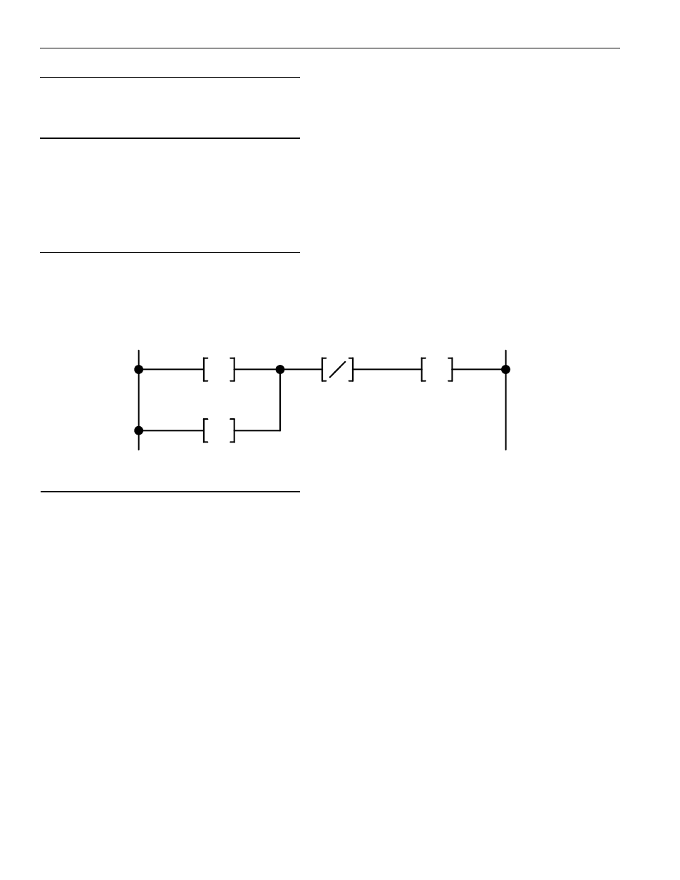
Discrete I/O
Channel Status
Channel Output
012
AND Coil
212
OR Coil
112
Ladder Diagram Example of ORing/ANDing Coils
Note: The "Pulse Register
Enable" coil (#302) is intended
for mass downloads.
When a pulse is created using this
mode, the new pulse does not
appear in the channel until the
unit is power cycled. This enables
pulses to be added faster in a
batch type situation.
When pulses need to be created
and take effect immediately,
"Create New Pulse" coil (#303)
should be used instead.
"Pulse Register Enable" coil
(#302) should be set to 0.
A pulse created with "Create New
Pulse" coil will take effect
immediately and not require the
unit to be power cycled.