Mode 5 operation, Mode 4 operation (cont’d), 7 output grouping & modes – Electro Cam PS-6144 Series User Manual
Page 71
5-7 Output Grouping & Modes
Figure 32—Mode 4 Example Application
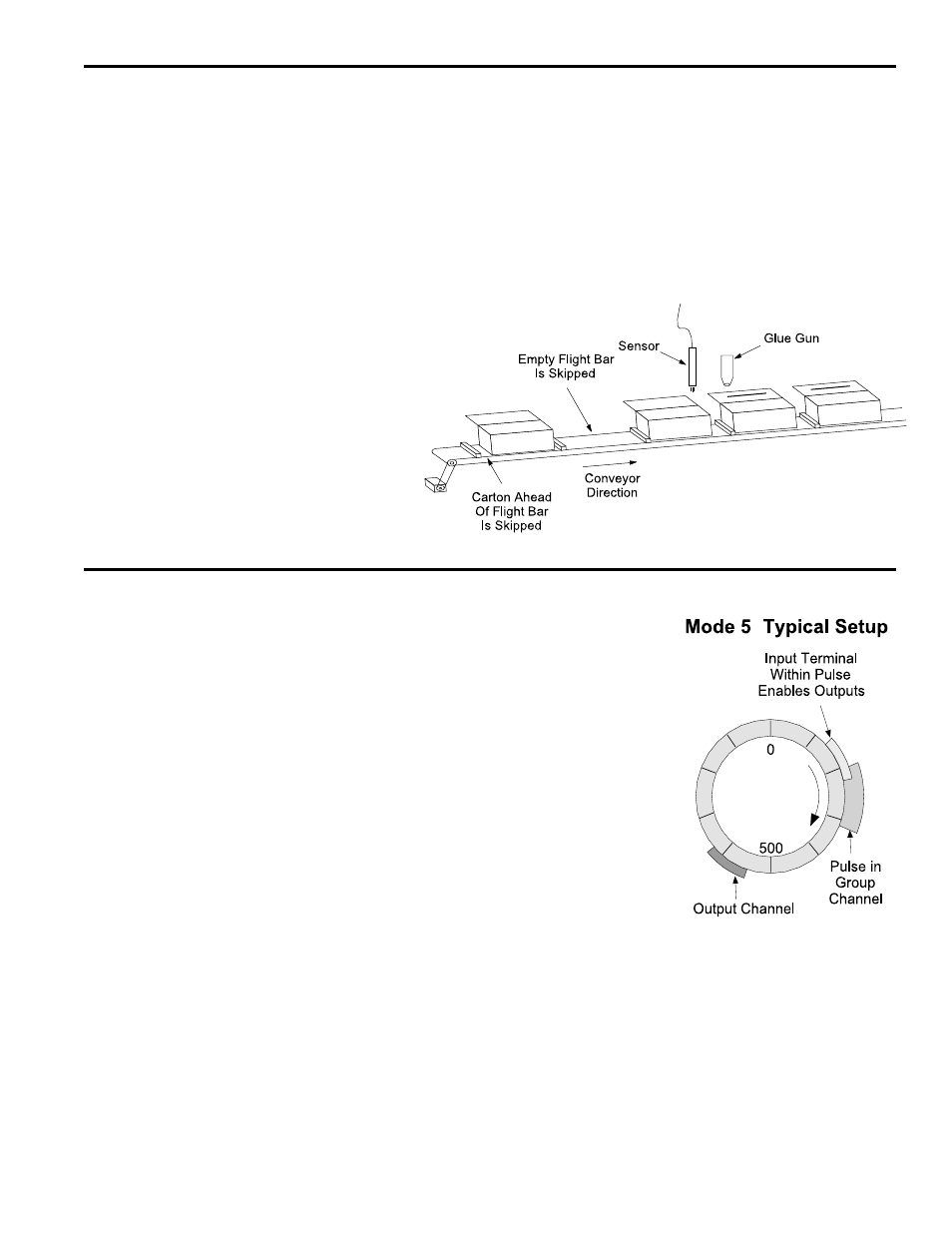
The glue gun will be enabled for one machine cycle
only if the sensor detects the leading edge of a
carton during the pulse programmed in the group
channel. If a carton is missing or incorrectly
positioned, the glue gun will not activate.
Mode 4 operation is appropriate for flight bar
conveyors, rotary index tables, and similar types
of machinery.
Mode 4 Operation (Cont’d)
Mode 4 Programming
See Figure 28 for input terminal and group channel assignments.
1. Program OUTPUT GROUPS to establish groups and modes.
2. Use OFFSET to program the absolute offset value for any Mode 4 groups.
3. Jog the machine to the point where the group input terminal will energize. Program
a pulse in the group channel that will turn on a little earlier than this point, and off a
little later. The shorter the pulse, the narrower the portion of the machine cycle in
which the input signal will enable the outputs.
4. Program setpoints into the output channels in the group. Remember that the lead-
ing edge of the pulse in the group channel will disable the output channels in the
group.
Mode 5 Operation
Description
Mode 5 operation is similar to Mode 4 operation,
with the following differences:
• In Mode 4, the leading edge of the input terminal
signal must occur within the pulse programmed
into the group channel.
In Mode 5, the group outputs will be enabled if
any portion of the input signal occurs within the
pulse.
• If the machine stops, the group outputs will be
disabled immediately. This prevents an operation
such as gluing from continuing if the machine
stops while the glue gun is on.
• If the machine is stopped and the group’s input
terminal is “on,” energizing the First Cycle Enable
terminal #15 on TB 1, Fig. 7, will re-enable the
outputs. This allows the operation to be complet-
ed on a product that was in process when the
machine stopped.
Details
See Figure 28 for input terminal and group channel assignments.
• Regardless of its programmed “off” point, the pulse in the group channel will end as
soon as any of the outputs in the group turn on.
• Each program in the controller can have different setpoints for output channels and
the corresponding group channel.
• MOTION ANDING and OUTPUT ENABLE ANDING can be used with outputs in a
Mode 5 group. Use MOTION ANDING to prevent the First Cycle Enable terminal
from re-activating the outputs while the machine is stopped.
• The machine position for a Mode 5 group can be set through OFFSET programming.