Controller input wiring (cont’d) – Electro Cam PS-6144 Series User Manual
Page 14
2-6 Installation & Wiring
Controller Input Wiring (cont’d)
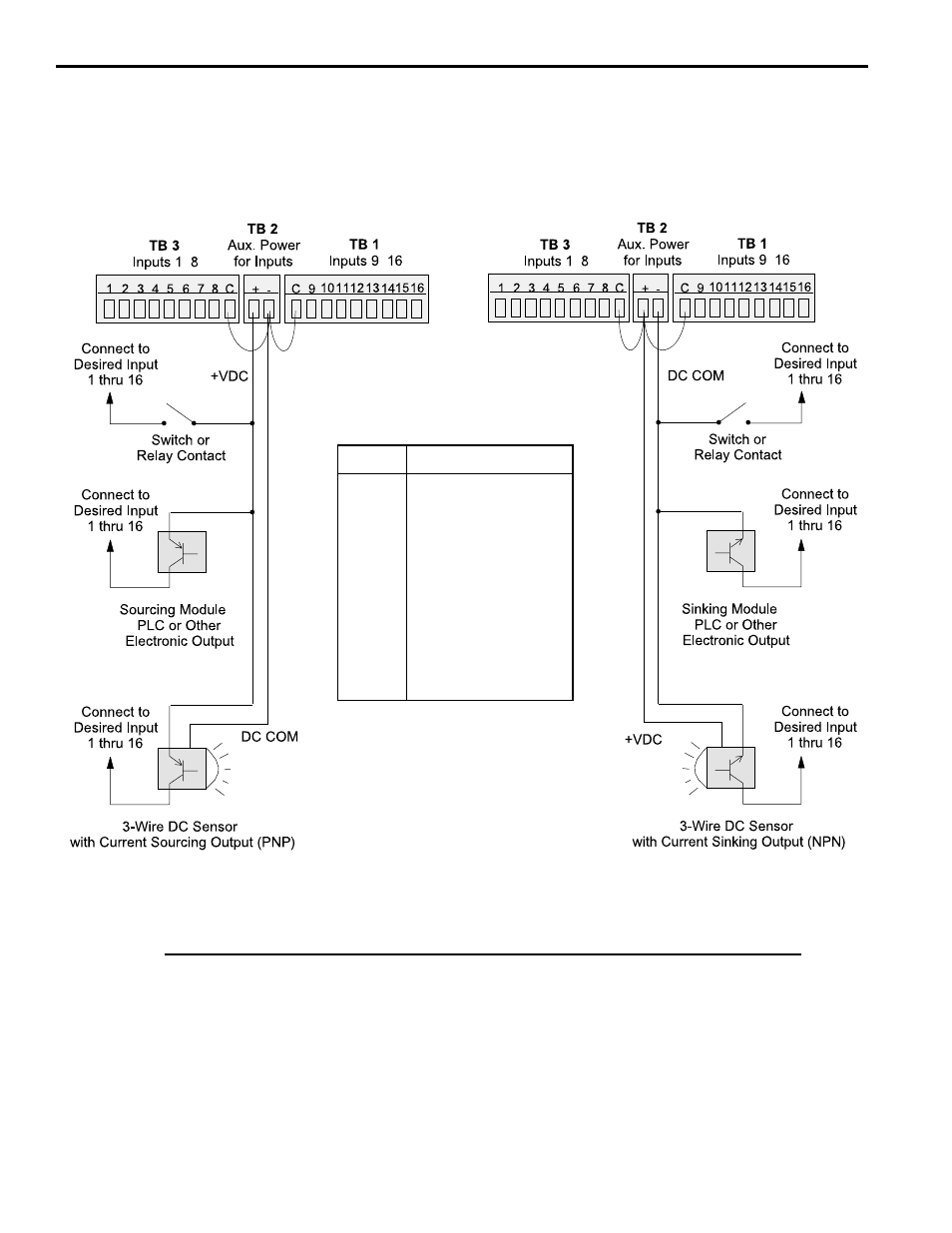
Figure 7—Controller Input Wiring (See Figures 5 & 6 for Terminal Block Locations)
-
-
Sourcing Devices
(+VDC is being switched)
Sinking Devices
(DC common is being switched)
Term.
Function
1-8
Program Select
9
Group 1 Input
10
Group 2 Input
11
Group 3 Input
12
Group 4 Input
13
Group 5 Input
14
Group 6 Input
15
First Cycle Enable
16
Output Enable
Input Wiring Guidelines
•
Voltage from TB 2 will be the same as the voltage supplied to the controller.
•
Each input powered from TB 2 will draw 11 mA at 24 VDC. TB 2 is fused at 1/4 amp.
•
Inputs will operate with voltages from 10 to 30 VDC.
•
An external power supply can be used instead of TB 2 to power inputs.
•
A combination of mechanical and solid state devices can be used.
•
TB 1 can be wired for sourcing while TB 3 is wired for sinking, and vice versa.
-
-