Mode 4 operation, Mode 3 operation (cont’d) – Electro Cam PS-6144 Series User Manual
Page 70
5-6 Output Grouping & Modes
Mode 4 Operation
Description
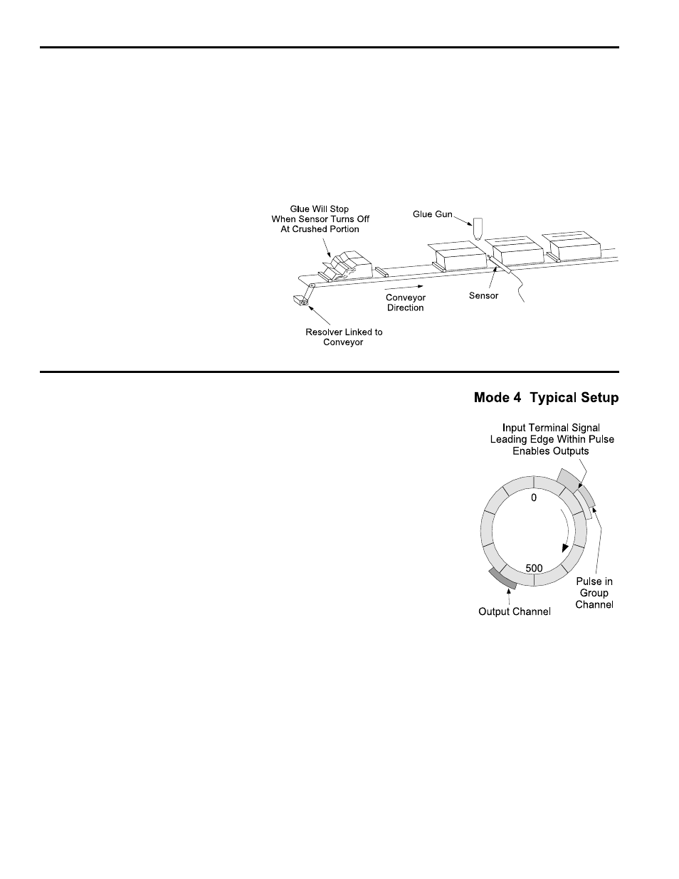
For a group in Mode 4, outputs will be enabled to
turn on at their programmed setpoints for one ma-
chine cycle if the corresponding input terminal turns
on within a pulse programmed into the group chan-
nel. Outputs will be disabled at the start of the next
pulse in the group channel. See Figure 28 for input
terminal and group channel assignments.
Applications
Use this mode to check the presence and correct
positioning of a product before enabling the outputs
for this machine cycle.
Details
• The leading edge of the signal from the input ter-
minal must occur during the pulse in the group
channel. If the leading edge occurs before the
pulse, the outputs will not be enabled.
• Each program in the controller can have different
setpoints for output channels and the correspond-
ing group channel.
• Either edge of a pulse in the group channel can disable the outputs. If the resolver
shaft is rotating in the forward direction (position is increasing as shaft rotates) the
“on” edge of the pulse will disable the outputs. If the shaft is rotating in the reverse
direction (position decreasing as shaft rotates), the “off” edge of the pulse will disable
the outputs.
• MOTION ANDING and OUTPUT ENABLE ANDING can be used with outputs in a
Mode 4 group.
• The machine position for a Mode 4 group can be set through OFFSET programming.
Figure 31—Mode 3 Example Application
In this illustration the glue head will operate only
while the photo eye sees the top edge of a
carton. Gluing will stop on crushed or improperly
erected cartons when the eye loses sight of the
top edge.
Mode 3 operation eliminates the need to hard-
wire photoeyes and other sensors in series with
the corresponding controller outputs. Instead,
the sensor is “ANDed” with the output through
Mode 3 programming.
Mode 3 Programming
See Figure 28 for input terminal assignments.
1. Program OUTPUT GROUPS to establish groups and modes.
2. Use OFFSET to program the absolute offset value for any Mode 3 groups.
3. Program setpoints into the output channels in the group. Remember that the output
channels in Mode 3 will be enabled only while a signal is applied to the group termi-
nal.
Mode 3 Operation (Cont’d)