Mode 3 operation, Mode 2 operation (cont’d) – Electro Cam PS-6144 Series User Manual
Page 69
5-5 Output Grouping & Modes
Mode 2 Operation (Cont’d)
• Either edge of a pulse in the group channel can re-arm the input terminal. If the
resolver shaft is rotating in the forward direction (position is increasing as shaft ro-
tates) the “on” edge of the pulse will re-arm the terminal. If the shaft is rotating in the
reverse direction (position decreasing as shaft rotates), the “off” edge of the pulse will
re-arm the terminal.
• Each program in the controller can have different setpoints for output channels and
the corresponding group channel.
• MOTION ANDING and OUTPUT ENABLE ANDING can be used with outputs in a
Mode 2 group.
Figure 30—Mode 2 Example Application
M
ode 2 Programming
See Figure 28 for input terminal and group channel assignments.
1. Program OUTPUT GROUPS to establish groups and modes.
2. Use OFFSET to program the “Preset” value for any Mode 2 groups.
3. Jog the machine to the point where the group input terminal will energize. Using this
point as a reference, program setpoints into the output channels in the group.
4. Program a pulse in the group channel to disable the output channels and re-arm the
input terminal. This pulse must be after all of the output channels have completed
their functions, but before the input terminal will be energized.
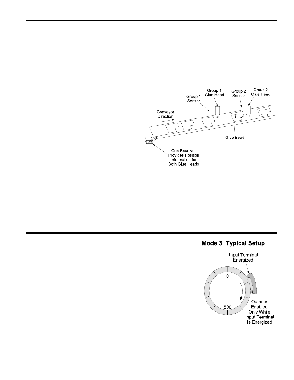
Mode 3 Operation
Description
Outputs in a group assigned to Mode 3 are
on only while their programmed setpoints are
on AND the corresponding input terminal is
energized. If the input is off, all of the outputs
in the group will be off, regardless of setpoint
programming. See Figure 28 for input termi-
nal channel assignments.
Applications
Use this mode where outputs should be ac-
tive only while a sensor or limit switch is on.
Details
• The group channel for a group operating in
Mode 3 has no effect.
• Each program in the controller can have
different setpoints for output channels in the
group.
• MOTION ANDING and OUTPUT ENABLE ANDING can be used with outputs in a
Mode 3 group.
• The machine position for a Mode 3 group can be set through OFFSET programming.
Two glue heads at different locations on the conveyor are
controlled independently by a single PLuS controller and
resolver. The spacing between parts being glued is random.
The sensors are connected to the input terminals for the
corresponding groups. When a sensor detects a product, it
resets the corresponding group position to the “preset”
values and enables the group outputs to turn on the glue
guns at the correct setpoints.
When parts are not present, the outputs will be inactive.
(continued)