Output wiring (cont’d) – Electro Cam PS-6144 Series User Manual
Page 17
2-9 Installation & Wiring
Output Wiring (cont’d)
PS-6144-24M17
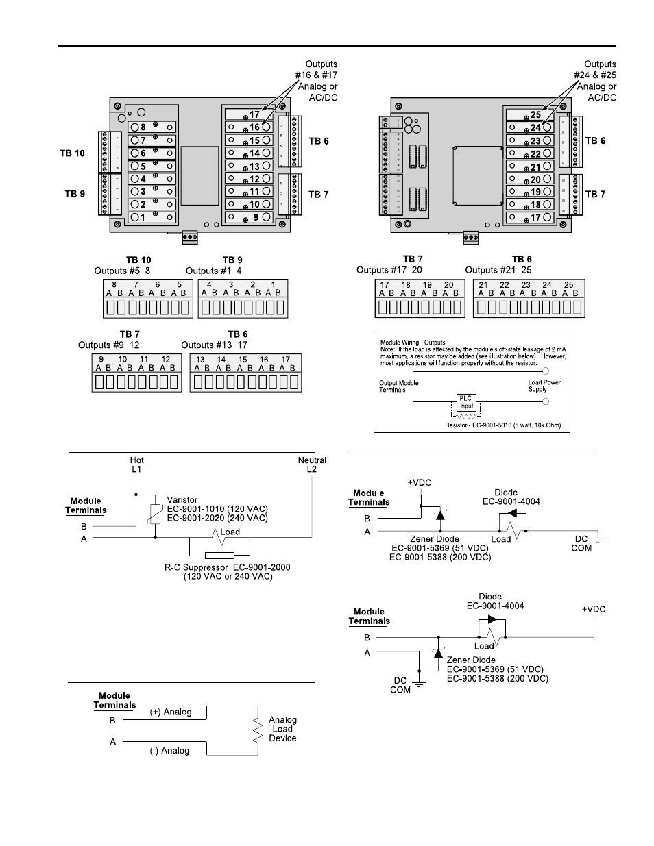
Figure 9—Wiring for Output Modules
Sourcing
Most applications will not need the varistor or R-C suppressor shown
above. However, when other switching devices are in series or parallel
with the AC module, voltage spikes may damage the module. Use one of
the following two methods to suppress voltage spikes.
• For infrequent switching, connect a varistor (MOV) across the terminals.
• For continuous switching, wire an R-C suppressor in parallel with the
load.
Most applications will not need the diodes shown above. However, highly
inductive DC loads may damage modules by generating voltage spikes
when switched off. Suppress these voltage spikes using one of these two
methods:
• Connect a Zener diode across the terminals. This will not significantly
increase the load turn off time. Voltage rating of the diode must be
greater than the normal circuit voltage.
• Connect a reverse-biased diode across the load. This may increase the
load turn off time.
Sinking
PS-6144-24-X16-M09
• Analog output modules source the analog signal.
• No external supply is required.
• Analog output signals are isolated.
Analog Output
-
- --
-
-
-
-
Electro Cam
DC Output
AC Output