1 mounting instructions for 1803r – Micromod MOD: 30ML Installation User Manual
Page 35
MOD 30ML Multiloop Controller
MECHANICAL INSTALLATION
29
2.4.1 MOUNTING INSTRUCTIONS FOR 1803R
Parts Included:
1. Display/Faceplate assembly to be mounted on the panel – This includes a flat gasket which is glued
to the bezel to provide a seal between the faceplate and the panel surface.
2. Instrument assembly and cable – This will be installed behind the panel and connected to the
faceplate.
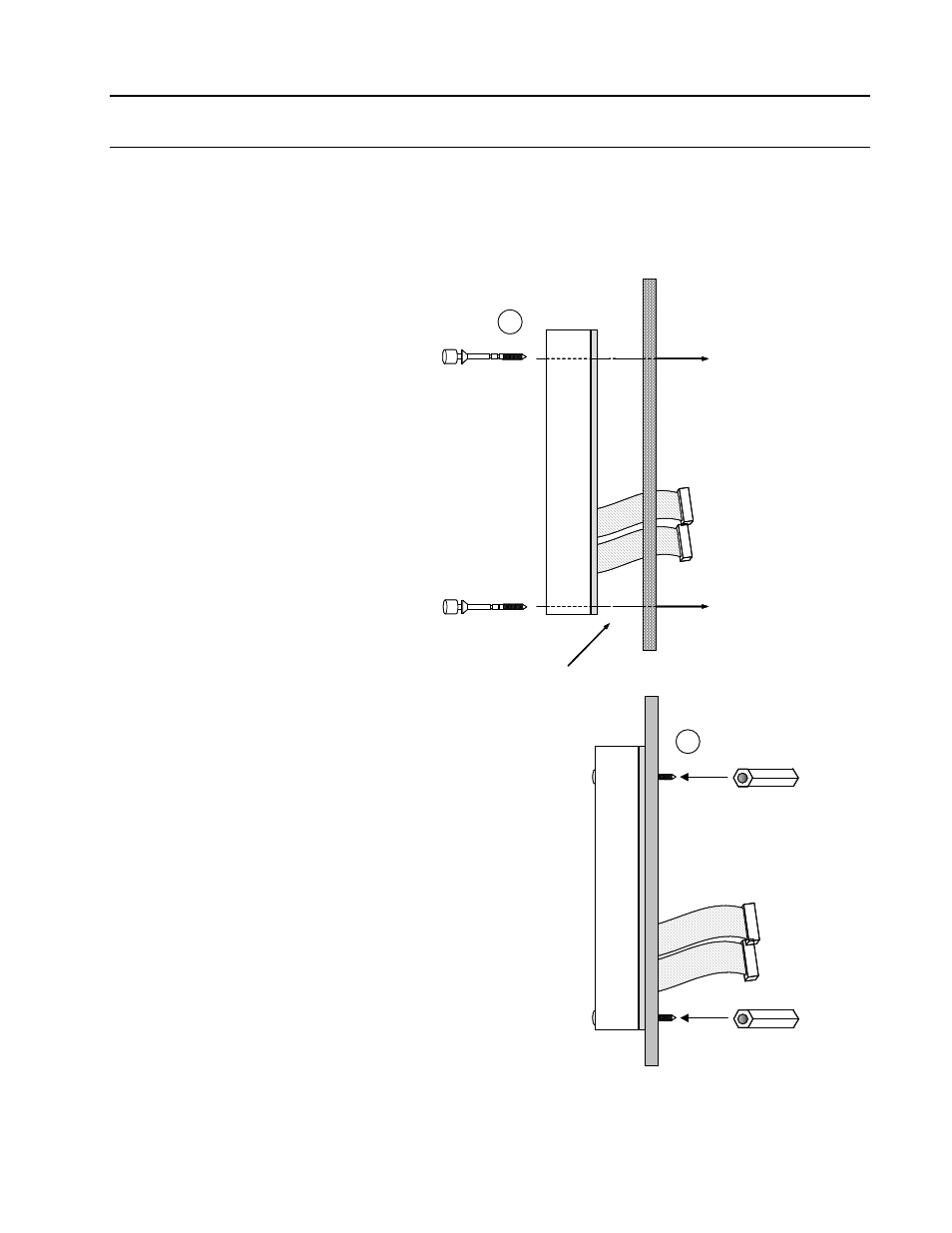
Mounting the Display Assembly:
Refer to the Mounting Diagram in Figure
2-3.
The two holes (0.152 inches) are for
positioning the faceplate.
Remove the two #6 Phillips head screws
which attach the metal cover to the back
of the faceplate.
Remove the hex spacers from between
the display and the cover.
The cables between the display and the
circuit board inside the cover can be left
attached. Pass the display through the
panel hole from the inside.
Assemble the faceplate to the outside of
the panel. The two faceplate screws go
through the holes in the panel cutout.
Note: The faceplate/display assembly
can be mounted anywhere on the panel
where there is clearance behind the
panel for the cover and the cable. It is
generally possible to complete the
installation without disconnecting the flat
cables. If it is necessary to disconnect a
cable, use a small screwdriver to
carefully pry the connector from the
circuit board. Pulling it off by the cable
may damage the connector.
Re-attach the two hex studs to the
faceplate screws, with the counter-bored
end towards the display.
Tighten the screws enough to compress
the gasket slightly.
Panel
1
Gasket
Panel
1
Gasket
Panel
2
Panel
2