Magnum Venus Plastech Megaject RTM Pro Revison 7_0 User Manual
Page 7
Megaject RTM Pro Manual – Revision 7.00 – 13
th
APRIL 2006
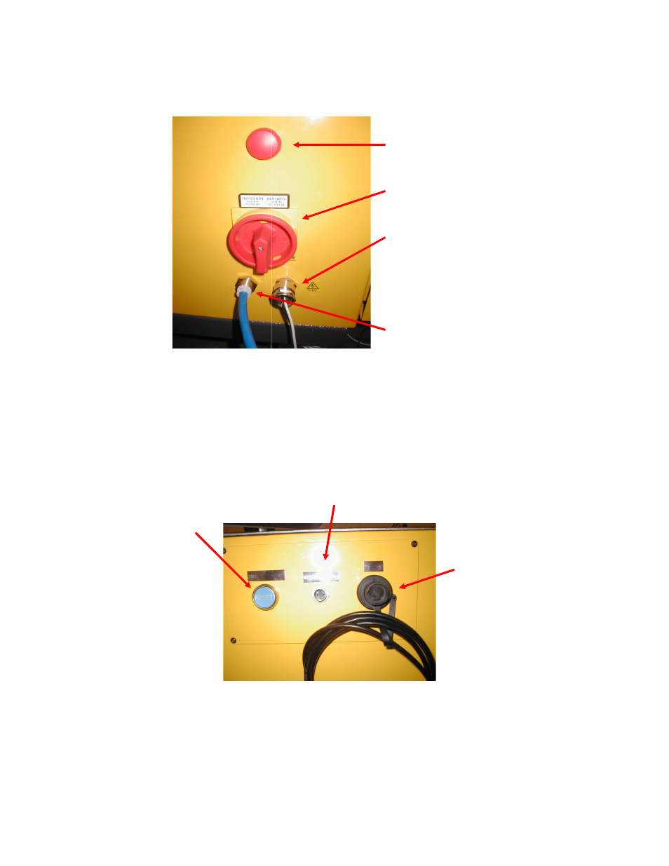
Figure 1.2 illustrates the main electrical isolator, power and air connections for the
Megaject RTM Pro. These are located on the side of Bay 1.
Figure 1.2 – Electrical isolator and service connections
Above the electrical isolator, towards the top of the machine, is the panel shown in
Figure 1.3. A connector is provided to allow an external resin level sensor to be
connected to the machine in addition to an Ethernet socket, which allows a PC to
connect to the control system. The blue RESET button is used for the safety circuit,
and must be pressed when the machine is first powered-up, or after an emergency stop
condition, when the e-stop button has been released.
Figure 1.3 – Reset button and external connections
Bay 2 contains the resin pump, catalyst pump, progressive catalyst ratio system and
pneumatic control and preparation components, and is shown in Figure 1.4.
E-Stop RESET
Button
Resin level sensor connection
Ethernet socket
Power indicator
Isolator switch
Electrical supply
Air supply
- PATRIOT 10:1 ADHESIVE SYSTEM (66 pages)
- PATRIOT PAT-CP-0550 (29 pages)
- PATRIOT 10 PAT-PH-10000 (34 pages)
- PATRIOT 7 PAT-PH-7000 Series (48 pages)
- PATRIOT 5 PAT-PH-5000 Series (42 pages)
- PATRIOT 4-1_4 PAT-PH-4250 (34 pages)
- PATRIOT 3-1_4 PAT-PH-3250 Series (36 pages)
- PATRIOT HV PAT-LS-49090 (33 pages)
- PATRIOT 1-3_4 PAT-LS-24050 (60 pages)
- PATRIOT 1-1_4 PAT-LS-12270 (66 pages)
- PATRIOT SS PAT-CCP-LS-0590-SS (30 pages)
- PATRIOT PAT-CCP-LS-0590 (42 pages)
- PATRIOT PAT-CP-3000 (28 pages)
- PATRIOT PAT-CP-1530 (32 pages)
- PATRIOT PAT-CP-0980 (29 pages)
- PATRIOT PAT-CP-0245 (32 pages)
- PATRIOT FIRST TIME START-UP CHECK LIST - Internal Mix (1 page)
- PATRIOT DAILY START UP - External Mix (1 page)
- PATRIOT DAILY START UP - Internal Mix (1 page)
- PATRIOT PRE-START CHECKLIST - External Mix (1 page)
- PATRIOT PRE-START CHECKLIST - Internal Mix (1 page)
- PATRIOT SET-UP - External Mix (1 page)
- PATRIOT SET-UP FOR CHARGEABLE - Internal Mix (1 page)
- PATRIOT Multi-Color Gel Coater MVE-PAT-1500-X (60 pages)
- PATRIOT TESTING & ADJUSTING (55 pages)
- PATRIOT DAILY SHUT DOWN CHECKLIST - External Mix (1 page)
- PATRIOT DAILY SHUT DOWN CHECKLIST - Internal Mix (1 page)
- PATRIOT SPRAY FAN SETUP - External Mix (1 page)
- PATRIOT SPRAY FAN SETUP - Internal Mix (1 page)
- PATRIOT FIRST TIME START-UP CHECK LIST - External Mix (1 page)
- UltraMAX VHPC-1100 Series (25 pages)
- UltraMAX VHPC-4200 Series (26 pages)
- UltraMAX VHPC-3200 Series (39 pages)
- UltraMAX VHPC-2200 Series (34 pages)
- UltraMAX VHPC-2000 Series (32 pages)
- UltraMAX VHPC-1200 Series (25 pages)
- UltraMAX VHPC-1000 Series (38 pages)
- UltraMAX MULTI–COLOR GELCOATER MVG-1400-X-1 (50 pages)
- UltraMAX MVP Installation & Set-Up (2 pages)
- UltraMAX Shut-Down Checklist (1 page)
- UltraMAX Start-Up Checklist (1 page)
- UltraMAX Pre-Start Checklist (1 page)
- UltraMAX Start-Up Sheet Quick List Instructions (1 page)
- UltraMAX Installation (1 page)
- UltraMAX HVLS-1000 Series (40 pages)